
Written by Richard Ashton
Part one
The first Cummings and Wilson projectors were first made just after the First World War. A company partnership was formed to manufacture cinema projectors under the heading Australian Biograph designed and manufactured by Cummings and Wilson. The company was headed by James Cummings and Harold Wilson who together designed and manufactured their machines at 29 Alberta Street Sydney.
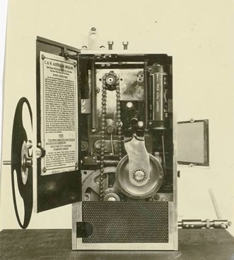
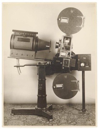
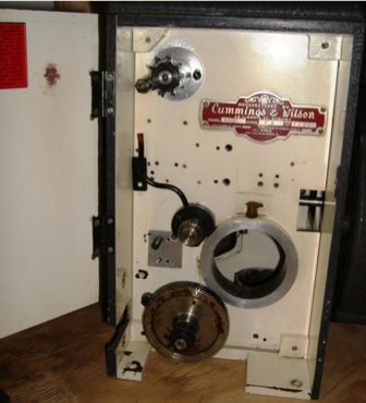
C&W Model D 35mm motion picture projector. Note the front shutter and rear framing handle of this early model. See also the springs on either side of the main plate compensating for it weight. The U shaped hole at the bottom left for the drive gear to the main shaft.
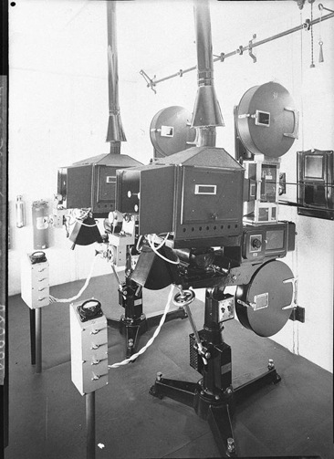
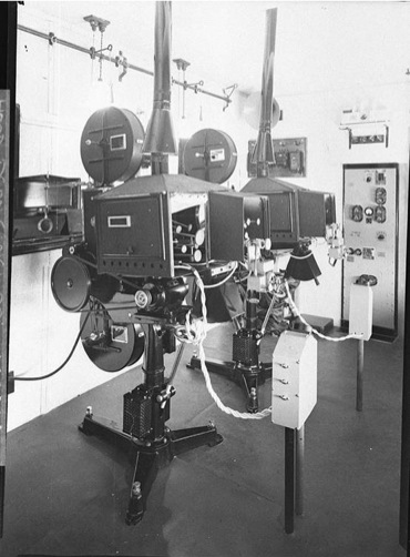
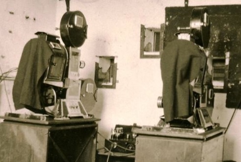
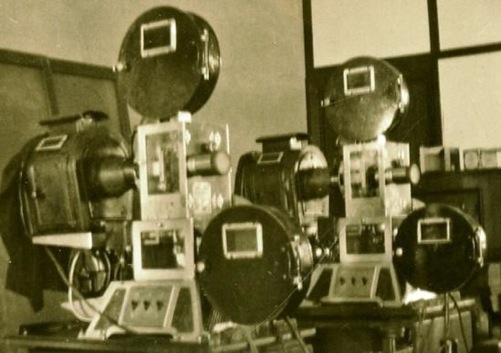
Two brand new C&W projectors on Raycophone bases installed at Kings Theatre Ashfield Sydney NSW in 1937.
Pictures by courtesy of the Hood Collection of the Library of NSW.
There are two distinct types of C&W projector mechanisms. The first and earliest type is one in which the framing is activated by lifting and lowering the intermittent mechanism and driving shafts and sprockets as one unit independently of the film gate, thereby revealing the film image to the lens at different vertical positions.
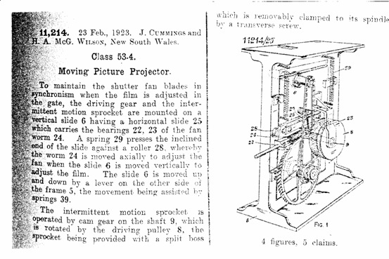
The initial patent applications were made to the patents offices of Commonwealth of Australia, Great Britain and U S A in 1923. It took 2 years till April 1925 before these were granted in the case of US application.
The US patent application said.
… the object of the invention was to provide a simple and efficient driving gear for the purpose of (a) driving the film actuating mechanism. (b) masking the film. (c) synchronizing the fan (Shutter). and further to, provide a simple and efficient driving and controlling gear for the purposes of driving the films actuating mechanism, masking the film and synchronising the fan shutter.
A further object of the invention is to provide a simple means of attaching the intermittent sprocket to its shaft so that it may be easily removed for replacement.
Further objects were, to provide a driving and controlling mechanism which would be inexpensive in the first cost and maintenance and which shall be silent in operation.
Also a method of attaching the intermittent movement sprocket to its shaft so as to be readily removable and easy to replace, and not requiring experts was featured in the patent applications.
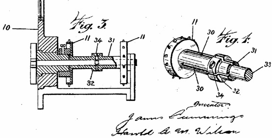
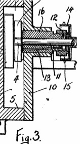
Fig.3 shows the simple means of attaching the intermittent sprocket to the shaft. It also shows how the collar with its grub screw (34) holds sprocket (11) in place and also adjusts to very fine tolerance the end float of the cross inside the case (10). Note the clever slots cut into the intermittent sprocket barrel (30). This patent number 11241 that can be seen on all C&W sprockets collar (32).
This is the US patent application drawing of the initial C&W projector and sprocket No. 11241 28February 1923
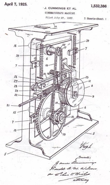
The next major improvement made to the projectors was the intermittent operating mechanism for the improved smoother and silent running of their machines. In this new invention (April 1929) the intermittent casing is shaped so as to provide an oil chamber or bath for the Maltese cross mechanism to run in. The patent application goes on to say…
The chamber is shaped so as to provide at its low portion a bath or well (6) for the reception of oil into which the mechanism dips.
It is also provided with an external lubricating cup or feed device which is joined to the upper portion of the chamber by means of a feed tube (19). There is inspection window (22) through which the level of oil can be inspected. There is a suitable drain off through removable plug or screw (21).
For the purpose of preventing the escape of lubricating oil from the casing the intermittent sprocket shaft (11) which carries the Maltese cross at its inner end is made to pass through a bush (16) in the removable side plate casing (10).
It is provided at or near its outer end with an internal annular groove (12) to collecting any oil that may escape from the oil bath down along the intermittent motion shaft.
This annular groove (12) is also provided with a downwardly inclined oil-way (13) leading from the lower portion of the groove to an exit aperture at or near the end of the bush which later stands just “proud” of the interface of the removable plate.
There are other minor oil spillage protections listed in the patent, an internal rib cast into the body to prevent or control the internal splashing of the oil. A “snifting” valve is also provided to allow the chamber to breath, and also to allow the case to easily emptied and refilled of oil.
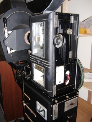
C&W Model D Series 3 No.409 is stamped manufactured 19.2.1930.
Note the maroon colour interior, a feature of early machines.
Note the large rear shutter of the Model D, framing handle at the front and drive gear at bottom. Also the slot in the front panel for provision of a front shutter
The British patent application of October 20, 1930 describes the rear shutter mechanism in the following terms. To prevent the overheating of the film and in one such arrangement the shutter had the form of the fan arranged intermediate the light box and operating mechanism. The fan shutter being so formed and disposed as to direct a stream of cooling air into the light box. The patent application which was accepted by the British patent office on September 22, 1932 went on to say. The fan is so arranged that the cooling air current is discharged from the shutter housing directly onto the film gate.
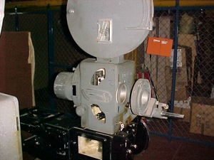
C&W Model D fitted to a Western Electric sound head. Note the C&W top and bottom spool boxes,the C&W base and the rear shutter as set out in the 1930 patent application of October 1930. Also the sound preamp in its own separate box and stand probably to be close to the cell but away from any mechanical noise of the projector.
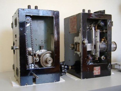
The flywheel side of the Model D
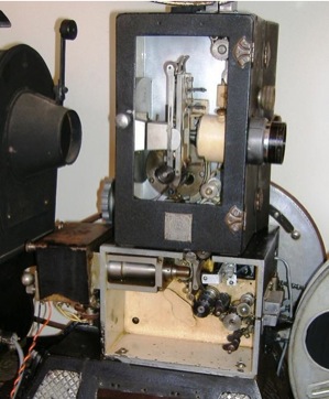
Model H series 6 No. 747
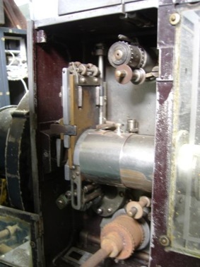
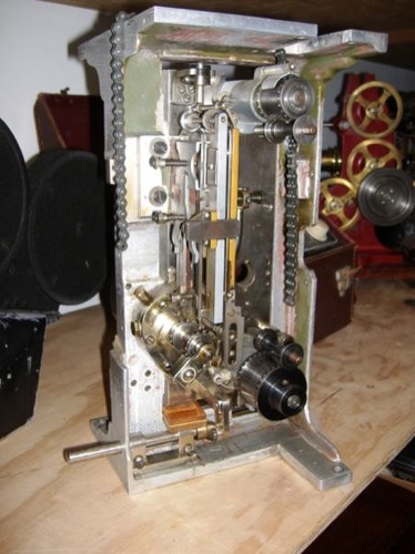
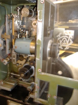
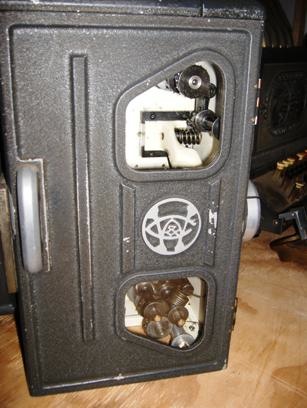
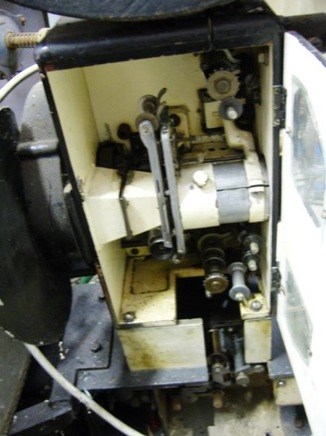
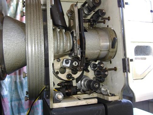
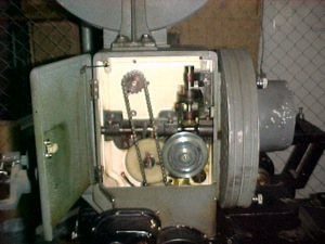
With the covers and lens mounting removed, the picture shows the slotted film guide at the bottom of the film gate around the intermittent movement. This allows for a change of position of the intermittent movement to remain in contact with the film regardless of the position of the main plate. The film gate is fixed to the body of the projector. The use of the framing handle at the bottom thereby corrects any inaccurate alignment of the film image in the gate. Correction can be made over 4 sprocket holes, two each way from centre position.
The Model D, G, and H, were the large sliding gate models and were very sturdy and different in construction from the P’s and J’s. These are often called “senior” models.
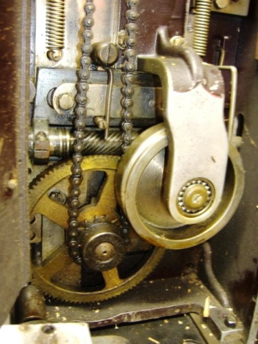
The plate complete with intermittent movement is spring loaded to counteract its weight, so that the framing lever activated at its base, could easily be moved up and down to correct the frame and stay in the position fixed. Note position of the main shaft driving gear, known as the “floppy dick” drive. Also note the much larger main shaft gear and the fine machining of the intermittent fly wheel and its roller bearing mounting bracket. The sliding plate keepers on either side of the projector frame can also be plainly seen.
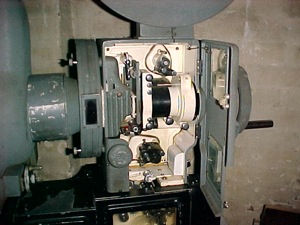
This Model H series 6 No. 747 large sliding gate model shows the operating side.
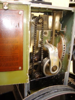
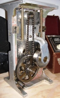
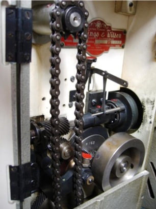
The flywheel side of the H6 No. 747.
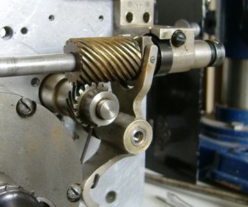
Note the robust compensating balance spring taking the weight of the main plate, also the roller bearing in the end of the flywheel support bracket. By the time Model H came on the market the mechanism for controlling the shutter position had been discontinued. A cross shaft fibre gear engaging with main drive gear carried the drive passed through the plate to the shutter shaft worm gear shaft now on the operating side. However the shutter still moved up and down inside its case in sync with the plate.
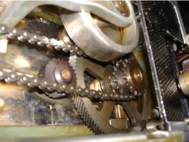
The main drive shaft with the two chain sprockets.
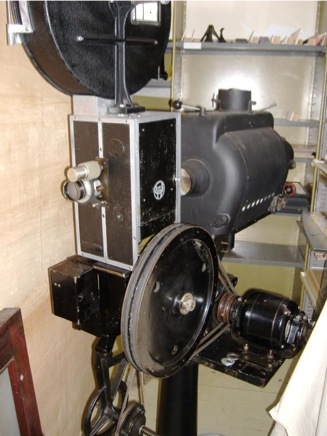
The complete Model H series 6 No. 747 mounted on a Western electric sound head with Australian made Calders ‘Trutrim’ DJ.
The second type of C&W projector came into being probably in 1930 when the call from Raycophone and others were set up to produce sound apparatus for far cheaper than the American system. It was said that the Australian Raycophone projector cost £1700, this compared very favorably with the US produced system at £11,000. Then followed what was described as… a short “Talkie War” in which US interests threatened to stop supplying theatres fitted with Raycophone equipment.This was quickly solved and Raycophone systems with C&W projector heads were installed into 375 Australian theatres by 1937.
The new C&W projector provided an intermittent casing that effectively rotated the complete movement around the centre line of the intermittent shutter. The design patent was applied for on May 6 1932. The patent number was 7266/32.
This achieves framing correction by rotating the intermittent movement itself. The ingenious twisting of the movement raises and lowers the film image to align with the shutter aperture and projecting lens.
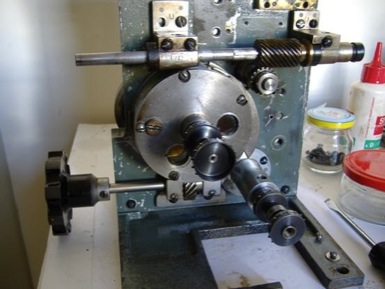
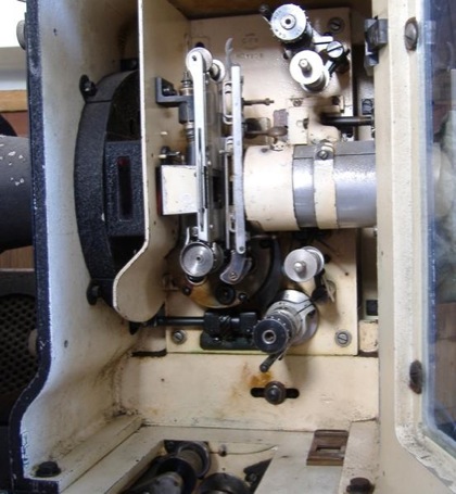
The Model P6 No.1066 shows the new circular rotatable intermittent movement.
The framing handle, shaft and gear is able to rotate the intermittent movement through four sprocket holes of one film frame image.
The amount of correction movement up or down was half a frame each way from a central position. This movement could be carefully made whilst the projector was running.
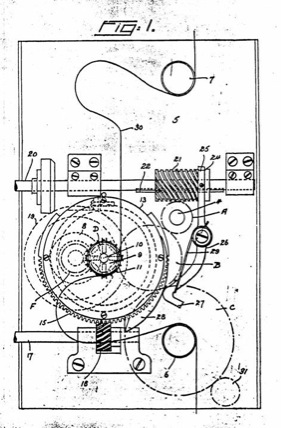
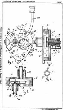
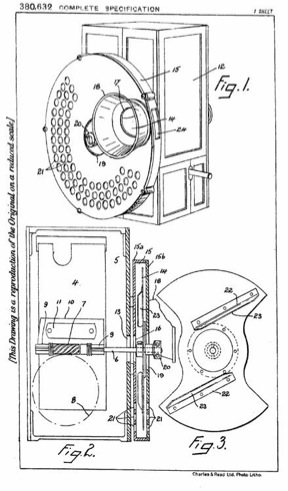
C&W Patent drawings of May 6 1932 showing the new projector design.
In the quest for a simple, economical in construction, method for the running and synchronizing the shutter blades a clever new design was necessary. To avoid ghosting effects of the picture on the screen due to incorrectly an adjusted shutter the opening and closing time must be constant regardless of any framing correction.
C&W partners Harold Wilson and Les Cummings son of James Cummings, who had passed in 1923, applied for the patent, which was surprisingly quickly given provisional acceptance by May 24 th, only 16 days later.
The design incorporated a train of gears to provide movements to the shutter and into the co-axially mounted idler gear and intermittent movement inside the rotatable case. To fully understand how the system works it is best described in the patents specification and with reference to these two drawings reproduced here.
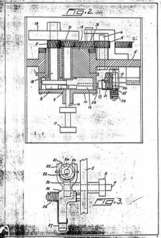
Patented drawings fig. 2 shows a cross-section of the gear train and the co-axially mounted idler gear and intermittent cam, Maltese cross and sprocket.
Fig. 3 shows the end elevation of the shutter shaft worm gear, fork and lever.
From the patent specification we read its rather complicated description.
If it is assumed that the mechanism is stationary the wheels A B E C and D all being in mesh are also stationary, while the wheel F is also a rest. If the shaft (17) is caused to rotate…the casing (13) is turned within the frame of the machine causing it to rotate round the shaft carrying the wheel D.
If the wheel F. being mounted upon the camshaft (18), which is of the centre line of the oil bath casing (13), is carried around the wheel D and its shaft by an amount determined by the rotation of the oil bath casing (13), but the wheel F being in mesh with wheel D is caused to turn and such movement of F gives rise to a corresponding movement of the cam (8) and hence the cross (9) on the intermittent sprocket shaft, with the result that the setting of the intermittent sprocket is altered. Hence movement of the means of controlling the shaft (17) causes of alteration of the setting of the intermittent sprocket (11) relative to the rest of the mechanism which relative movement causes film (30) to be moved so that masking of the films effected by the alterations of the position of the shaft (17).
To synchronise the simultaneous movement of the casing with the shutter, a cam was placed on the side of the intermittent casing, which engaged a lever and fork to move longitudinally the shutter shaft worm gears position with a twisting motion. In this way it adjusted the shaft’s rotational position with the casing, and therefore maintaining the shafts correct position with the masking movement, thereby eliminating ghosting effects on the screen.
The fork and lever to adjust the position of the shaft worm on the shutter shaft
This, rather ingenious C&W projector mechanism is to be manufactured with minor refinements for the next 25 years. This is a pretty fine recommendation of the quality of design, upholding their motto…of Quality and Honest Service.
C&W Film Gates. Top is the P5 and bottom the P6
The P5 89mm in length and P6 is 35mm longer and has two extra pressure shoes at the top, held in place by an extra pressure pad plate and spring. The cradle and its shoe is the same on both gates. The P6 gate is still in production to the final CP10.
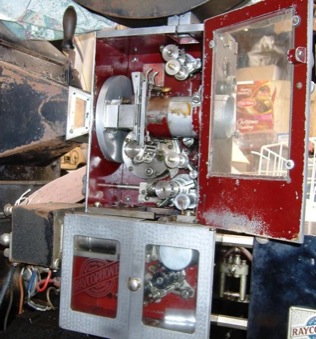
This C&W P5 No.237 mounted in a magnificent all Raycophone projector, sound head, arc lamp and base. Not the attractive maroon colour paint featured interiors.
After the introduction of sound, C&W made the mechanisms for other projector manufacturers such as Raycophone, RCA and Western Electric who made only the sound reproducing sections for their projectors. But in some cases where Raycophone made the whole machine, they installed C&W picture heads constructed to suit their sound heads. These are typified by the models P 3, P 5, P 7, P8, CP 7 and CP 10.
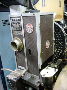
This C&W Model P 7 No. 703 projector head is mounted in a J3 Raycophone sound projector.
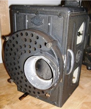
Note the heat sink and asbestos block near the fan aperture. The rear plate has vertical slotted holes to allow the fluted blades of the shutter to dissipate the heat generated from the arc lamp.
In this model J3 Raycophone projector complete with sound head, lower spool box, arc lamp and motor stand, houses the C&W P7 picture head.
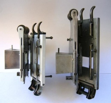
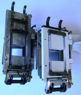
These P6 models No. 1065 and 1066 are completely C&W manufactured
They would bolt on, with suitable adapter and shafting, to any sound head and base just as with the Model D, G and H’s. In the case where the C& W projector is only part of the whole projector, the name plate is fixed to the mechanism and not the case. So we can know that in this case the C&W maker’s plates and mouldings which are on the projector body’s are C&W made.

The Raycophone J 6 is a small projector unit known as a “junior” model
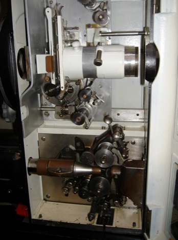
The C&W Model P series 6 No.871 is mounted on a Raycophone “junior” sound head, and base. The sound head now is fitted with a solar cell pick up head, replacing the original photo electric cell. The 8 volt exciter lamp and housing is mounted on the left of the sound mechanism case.
Two portable C&W P5’s with Raycophone “junior” sound heads and bases with small portable arc lamps ready for a show in a country hall by picture showman Ray Dean of West’s Talkies.
The doors of these P5 have had polished aluminum doors and maroon interiors.
Note also the smaller spool boxes and small arc lamps.
To make identification matters more difficult Cummings and Wilson often would take back earlier models and upgrade them as design improvements were made. They would redesignate them with the later model and series number, even though some of the body frames had a much earlier manufactured date stamped into the base.
To identify the model and the series of the C&W range is quite difficult; the confusion becomes even more difficult with the post war models, such as with the L 3 which is designated as P 8, which are a complete C&W projector heads.
This post war C&W Model L3 No.1776 with intermittent movement and driving gears removed shows its serial number as P8.
Note the position of the oil pipe feeding the centre shaft drive to the shutter shaft. There is no front opening panel on these later models.
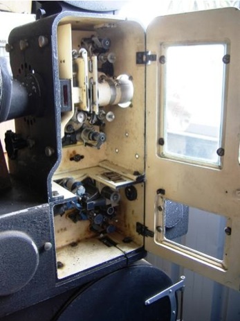
The Model L3 No. 1776 has grey wrinkle finish and is of the now post war distinctive two inspection window design.
The large rear shutter has convenient securing screws
Some C&W projectors like this J8 No.1877 have at 3 inch high mounting plate installed between the projector and the sound head which compensated for the soundtrack image being 19 frames ahead of the picture image.
In the some models like the J 3 the 19 frame compensation was achieved by lengthening the film path between the lens and the sound head by use of roller system. The P5, P6, J3 and the post war CP models are C & W mechanisms in Raycophone housings and incorporate that companies sound heads.
CP models are still of the twisting intermittent movement type. The framing handle is still at the rear of the projector which had a shaft and gear meshed to the completely round intermittent movement, which had teeth on its base as mentioned earlier. The correction to the film frame was made by twisting the intermittent movement moving the film in the gate up-and-down.
In this CP 7 No.1802, the Raycophone body in which the C&W picture head is mounted was made much longer to compensate for the 19 frame sound track to picture difference.
It is a little difficult in this picture to see the interesting rear shutter position which is behind the six nearled screws holding its cover. The two circular shaped doors at either end of the sound head contain the excited lamp and the preamp.
In the CP models the one door opens both picture and sound compartments for much easier threading. The sound head had major redesign more in the design of the RCA sound head.
The joint of the C&W CP7 No. 1802 projector head to the sound head shows a heat plate ahead of the internal shutter.
Note the threading lamp and holder. Hidden from view is the cut off blade mounted on the heat absorbing plate. Also note the slotted bolt in the bottom centre of the picture which is the chain drive adjusting roller on the flywheel side of the machine.
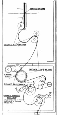
Film threading diagram of the CP 7
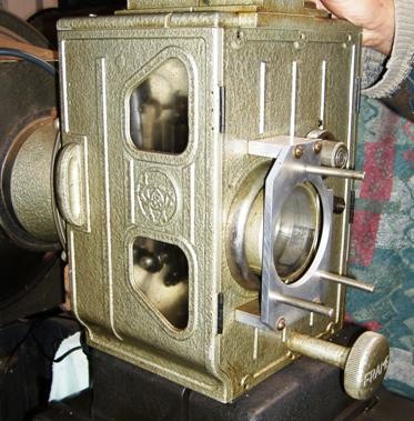
The Model M, Serial L, this one No. 2153, has the framing handle at the front of the machine. The aluminium bracket is for a Cinemascope lens installation.
Note the threading light at the top and its switch at the left of the door jamb, also intermittent sprocket support at the outer end of the shaft. Also note the much larger lens holder for taking new much faster modern lens.
The post war Model M Serial L No. 2153 has the shutter shaft on the flywheel side. The automatic cut off centrifugal bearing and activating lever passes through the main plate to the cut off blade.
This is a much improved the design. One of the failings of the earlier models was that, because of the heat of the arc lamp, the cut off mechanism bearing on the shutter shaft was “cooked” and would become seized on the shaft causing destructive failure. Note that the shutter adjusting yoke lever also passes through the main plate to the shutter adjustment cam on the intermittent movement.
The model M has a large externally mounted shutter at the rear of the body but still the basic C&W design concept.
The Model G was different in design then other C&W models. The design featured a contra-rotating rear shutter with a double bearing intermittent. The design was similar to the US Century and Australian made Super Standard. It featured a larger diameter lens mount for modern faster lens. As this machine was often used in drive-ins it also featured water/air cooled gates.
Photographs of the Ian Stimson Collection, TVW 7 Collection, AMMPT Collection, Richard Ashton Collection, The Hood Collection of the Library of NSW.
I thank all of you for the courtesy of allowing them to be shown.
All photographs and text Copywrite © 2007 AMMPT and respective owner. All rights reserved.