The C&W Raycophone Portable P 5

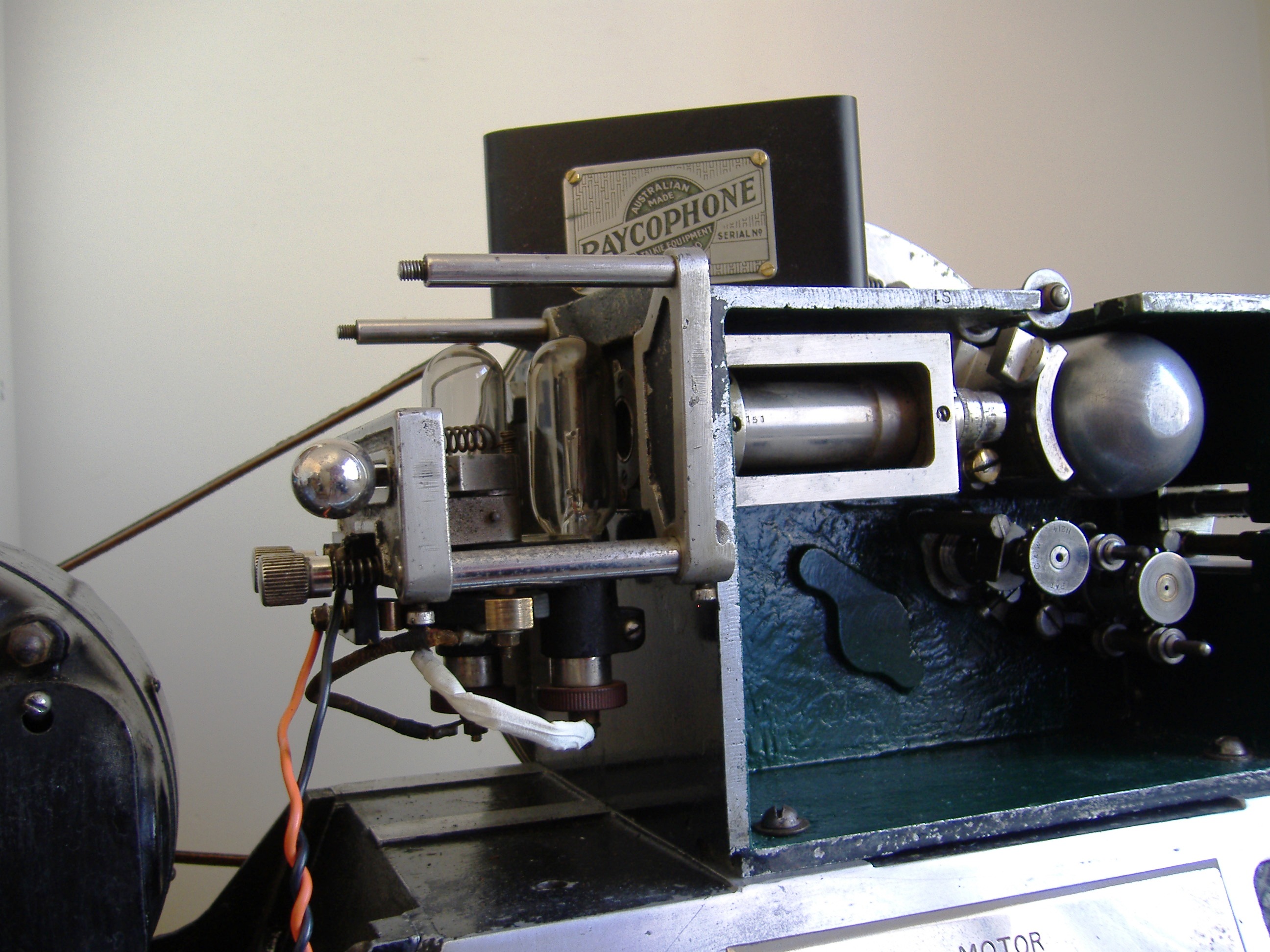
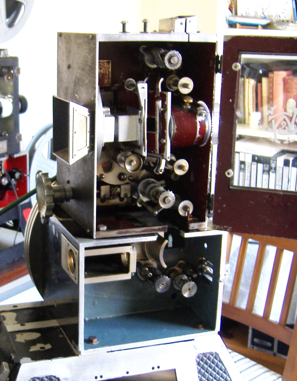
The C&W Raycophone Portable with the new C&W P5 projector head July 20 1932

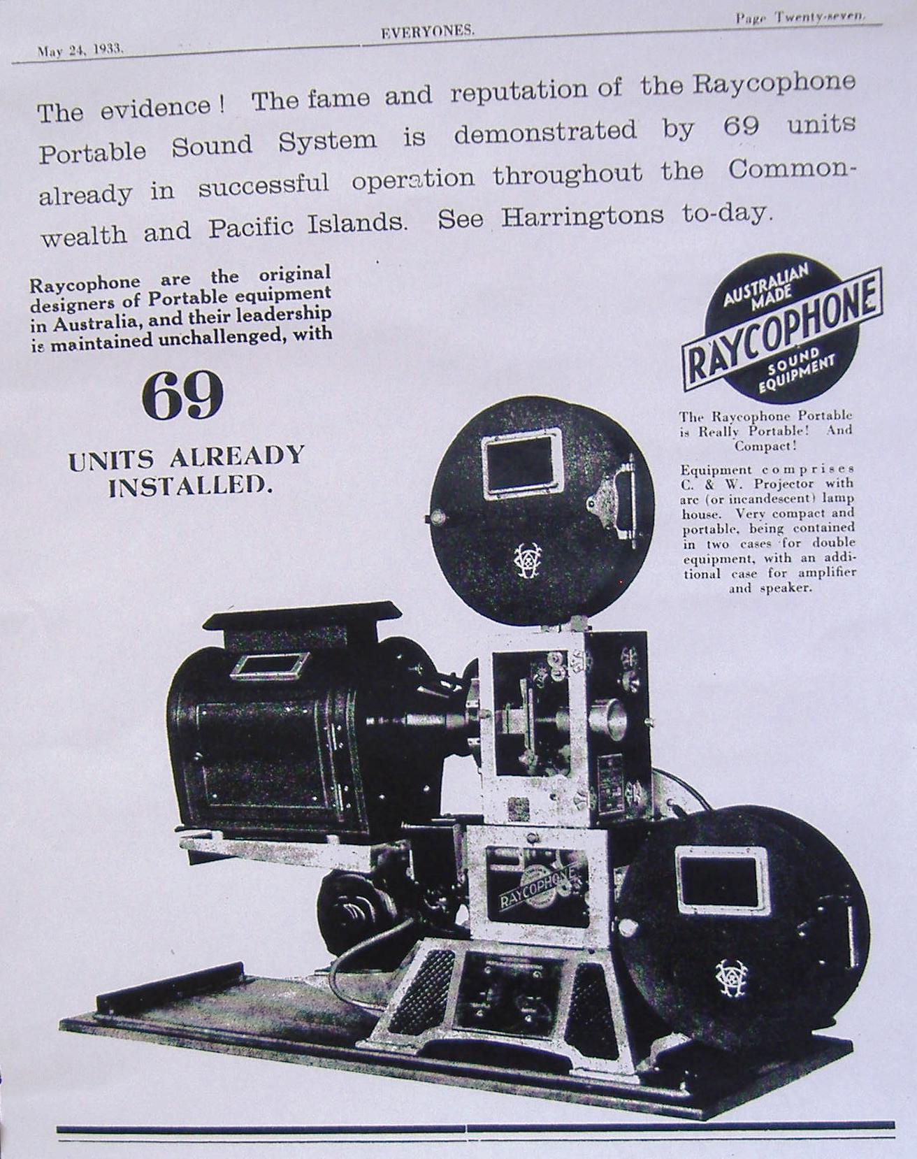
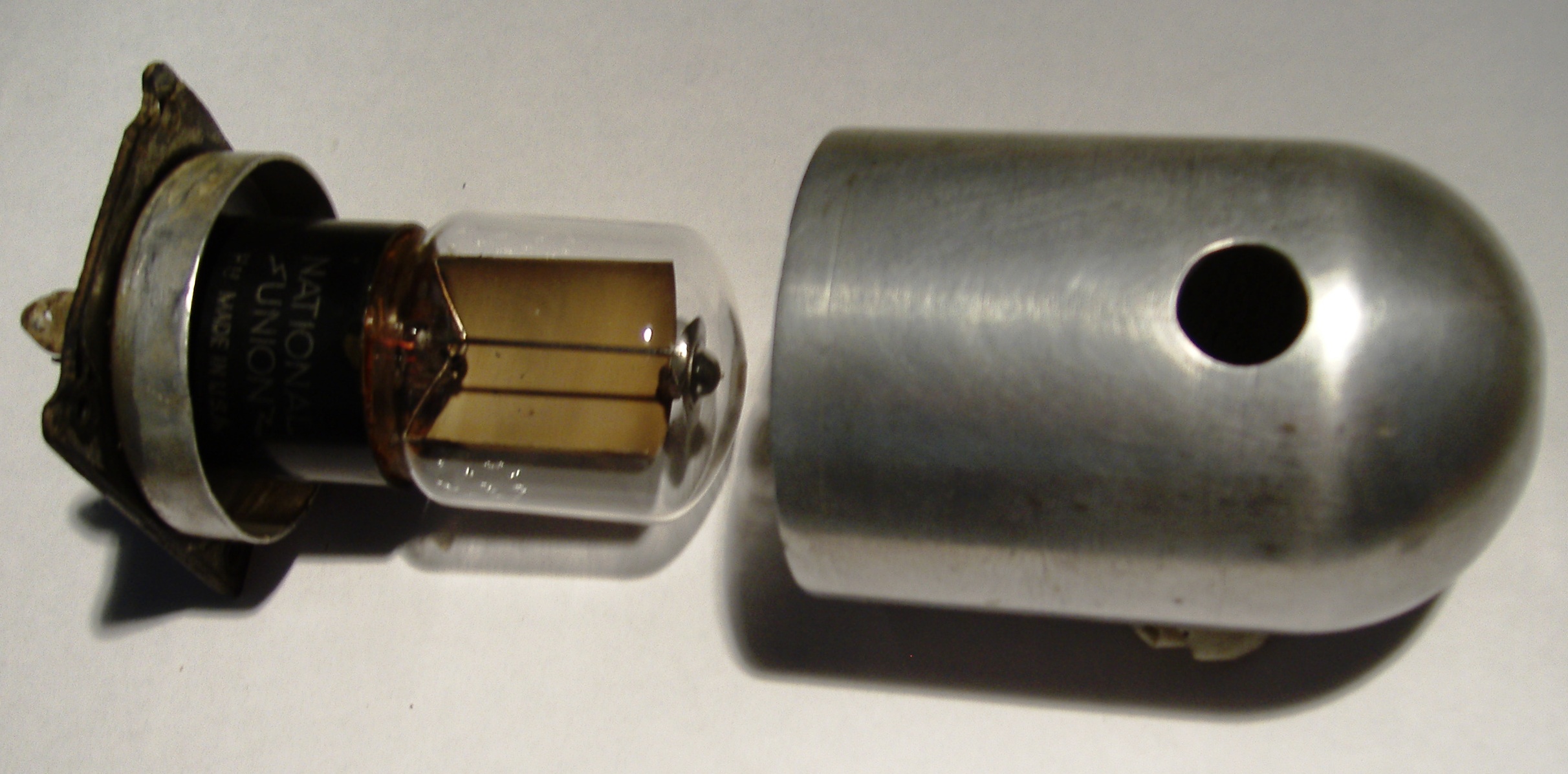
By  May 24 1933, there was now 69 C&W “Junior” fitted Raycophone portable projectors sold. By January 1934 these portables were being installed and used many hospitals and private homes in Sydney.

By November 1934 it is reported that 784 C&W projectors were now in use in Australia theatres

Raycophone 1

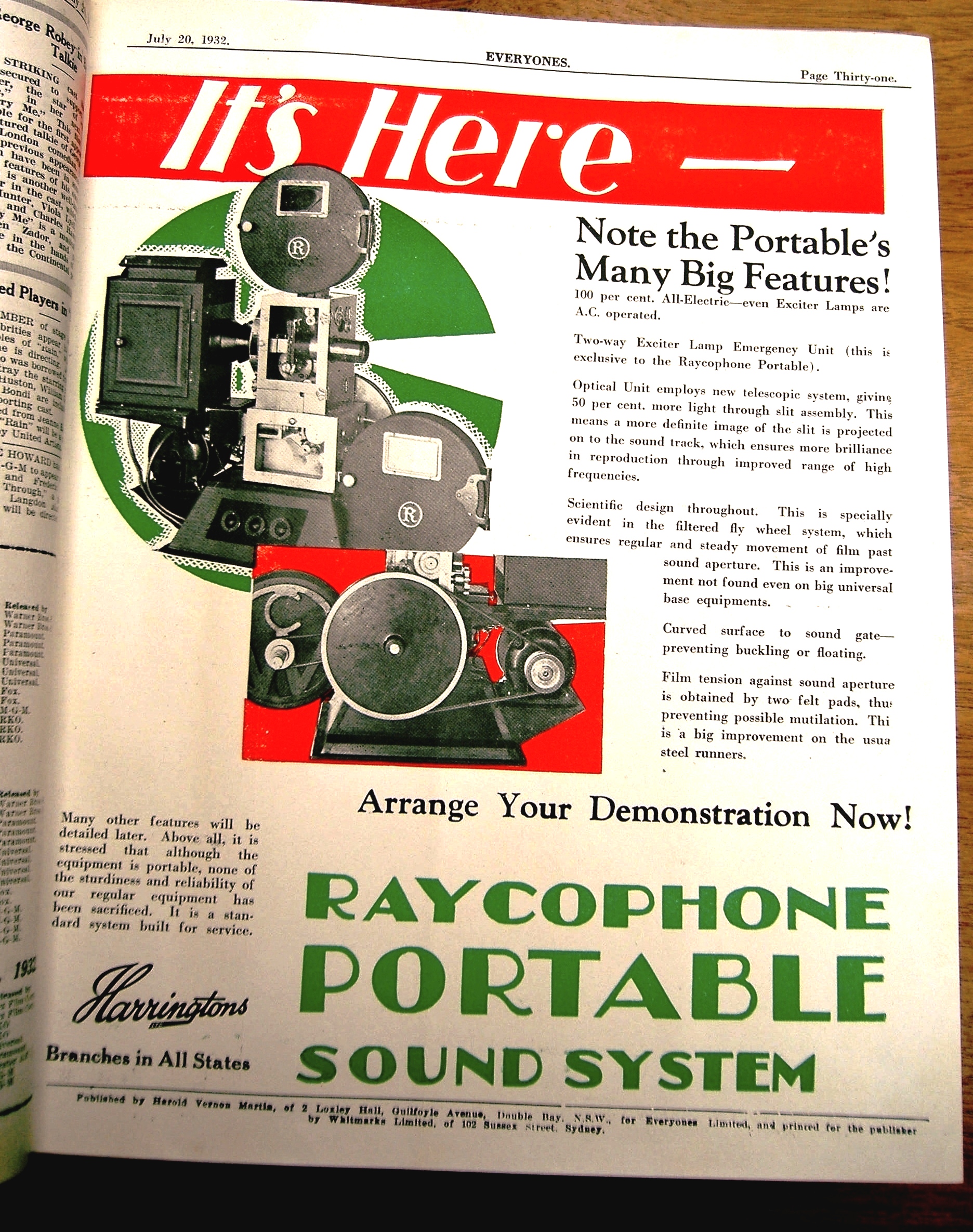
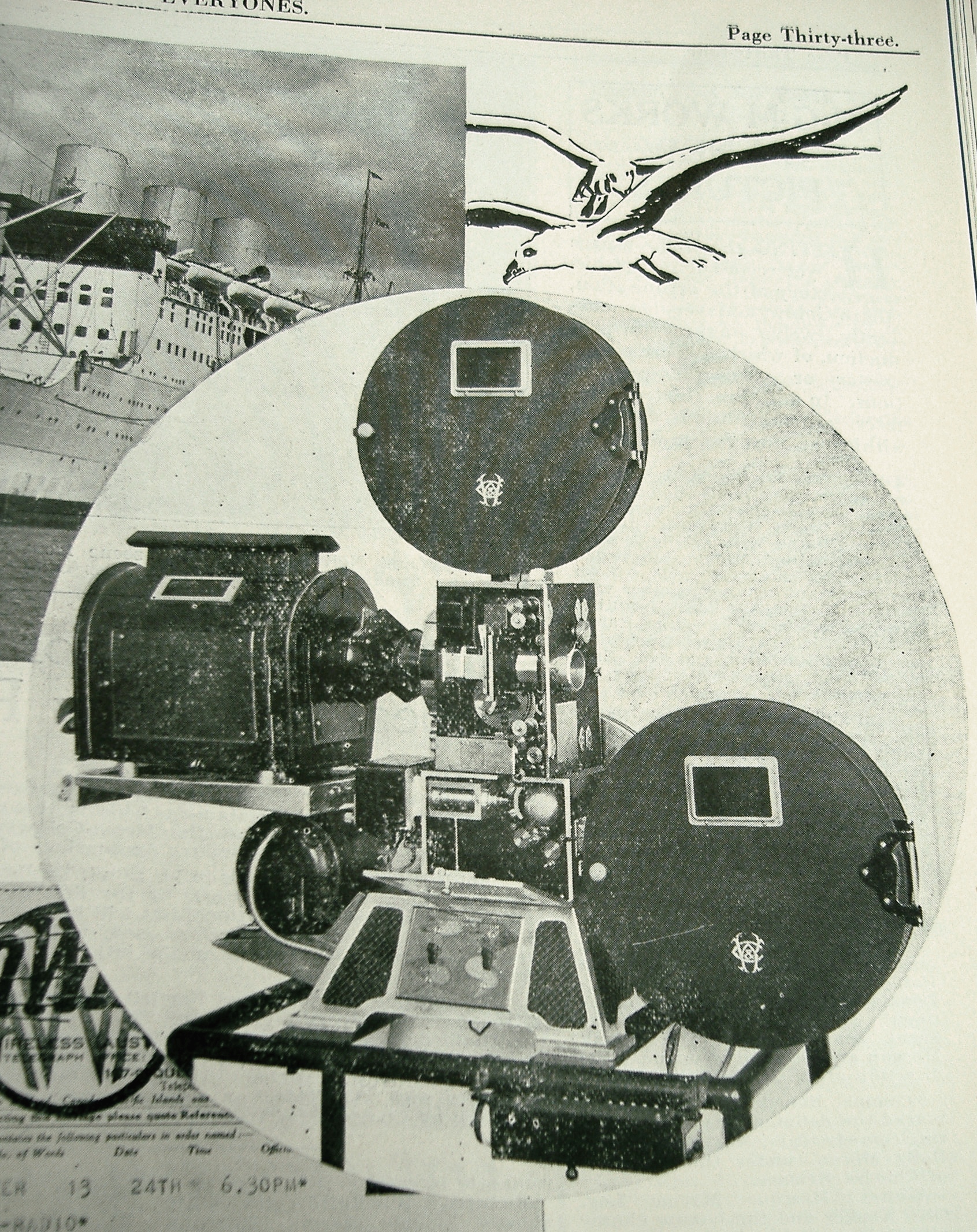
Advertisement and Photographs

raycophone 2

The announcement advertisement of the new Raycophone portable to be installed on P&O Cruise ship visiting Sydney


C&W Raycophone Portable projector P5 No. 71 with external shutter


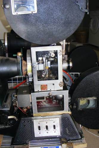
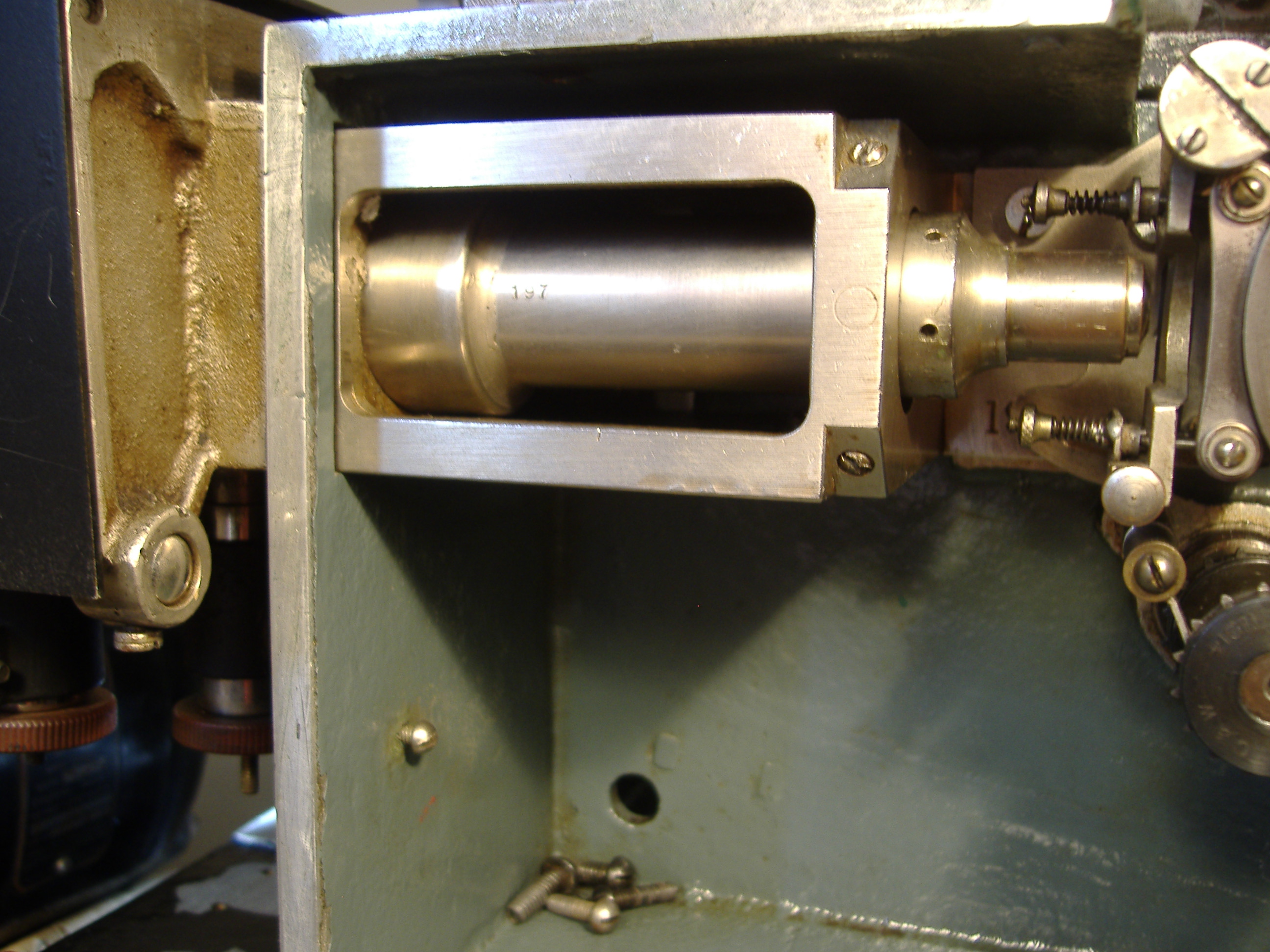
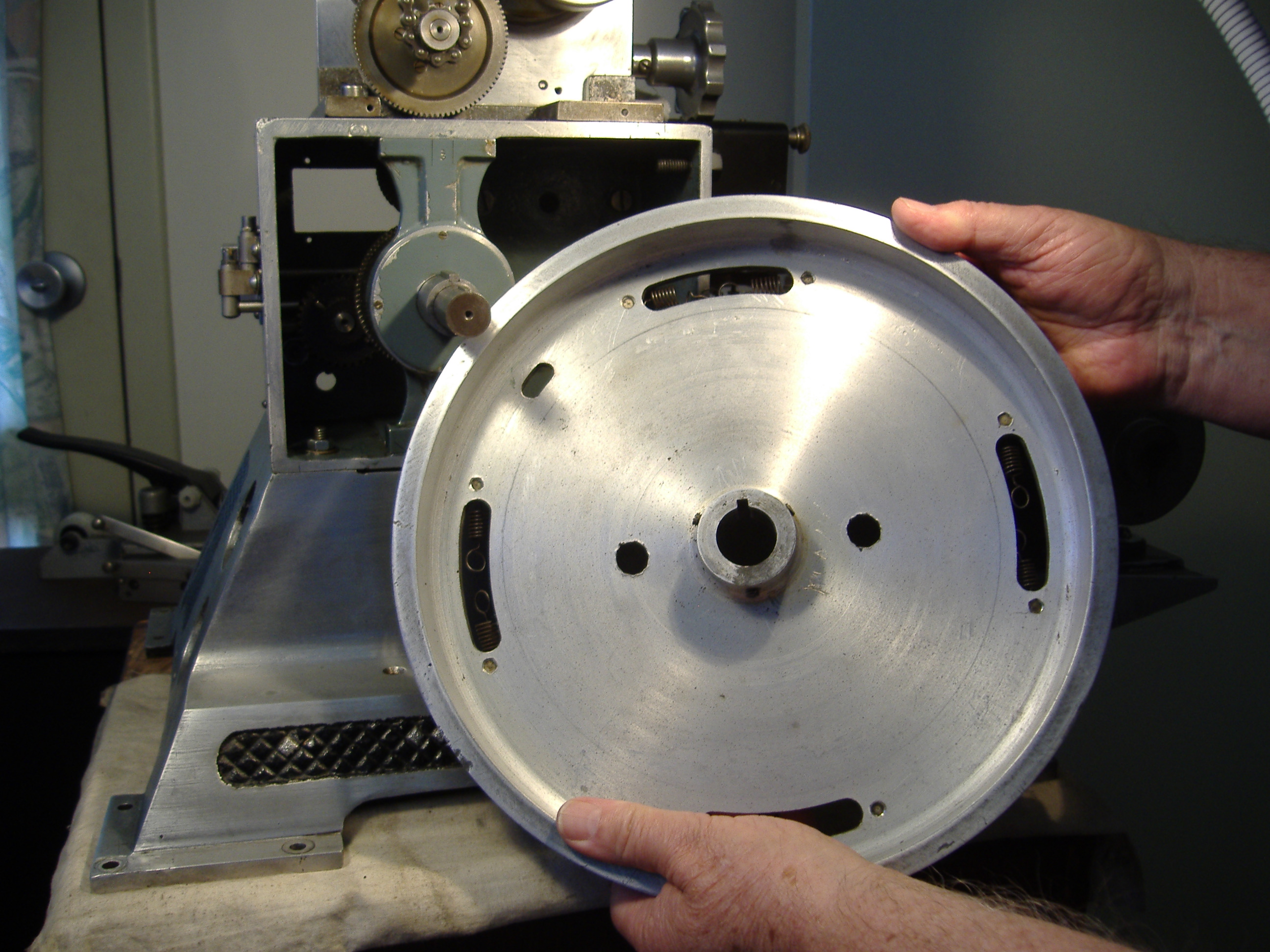
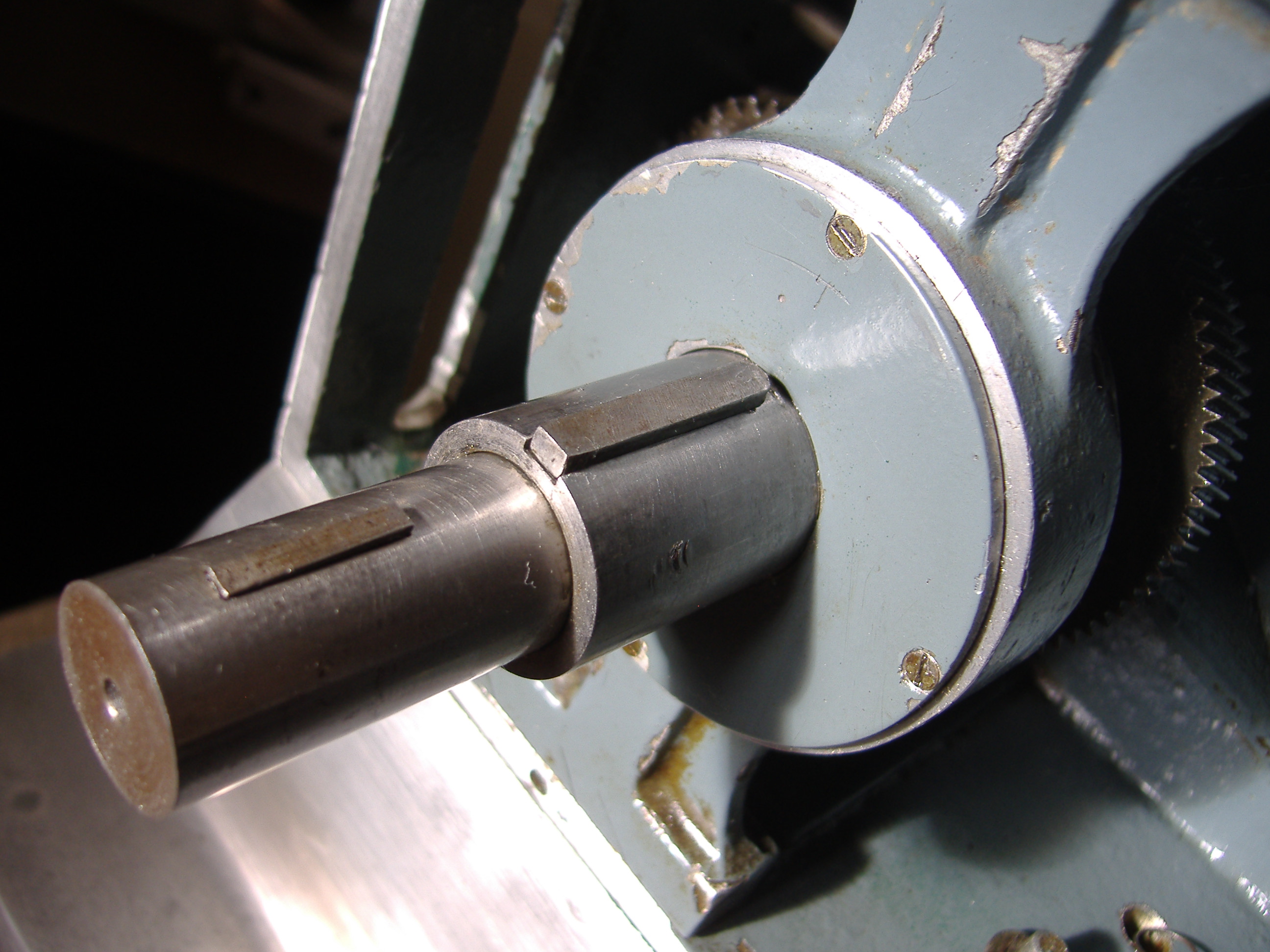
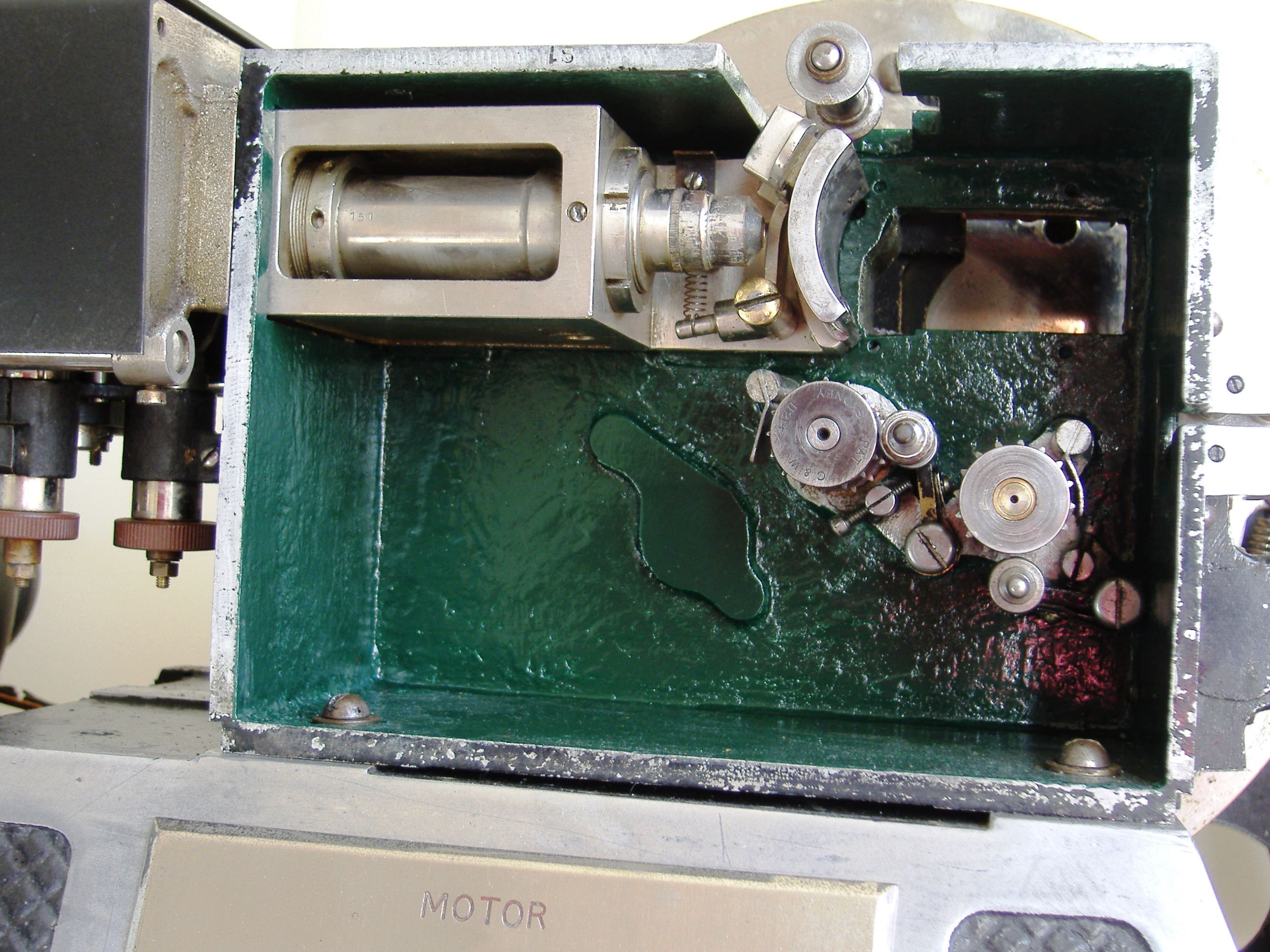
Assembling the Raycophone Portable Sound Head No.182

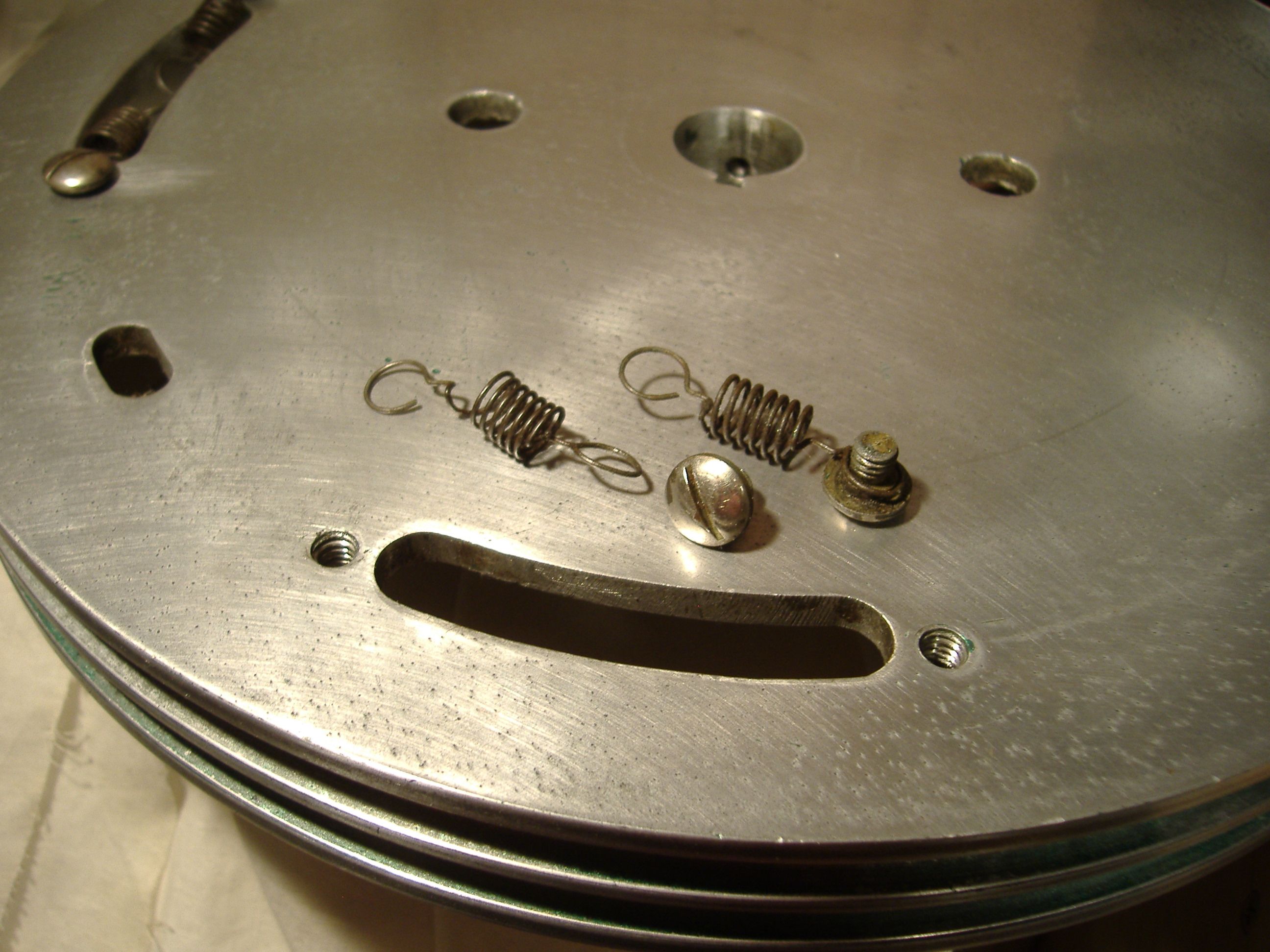
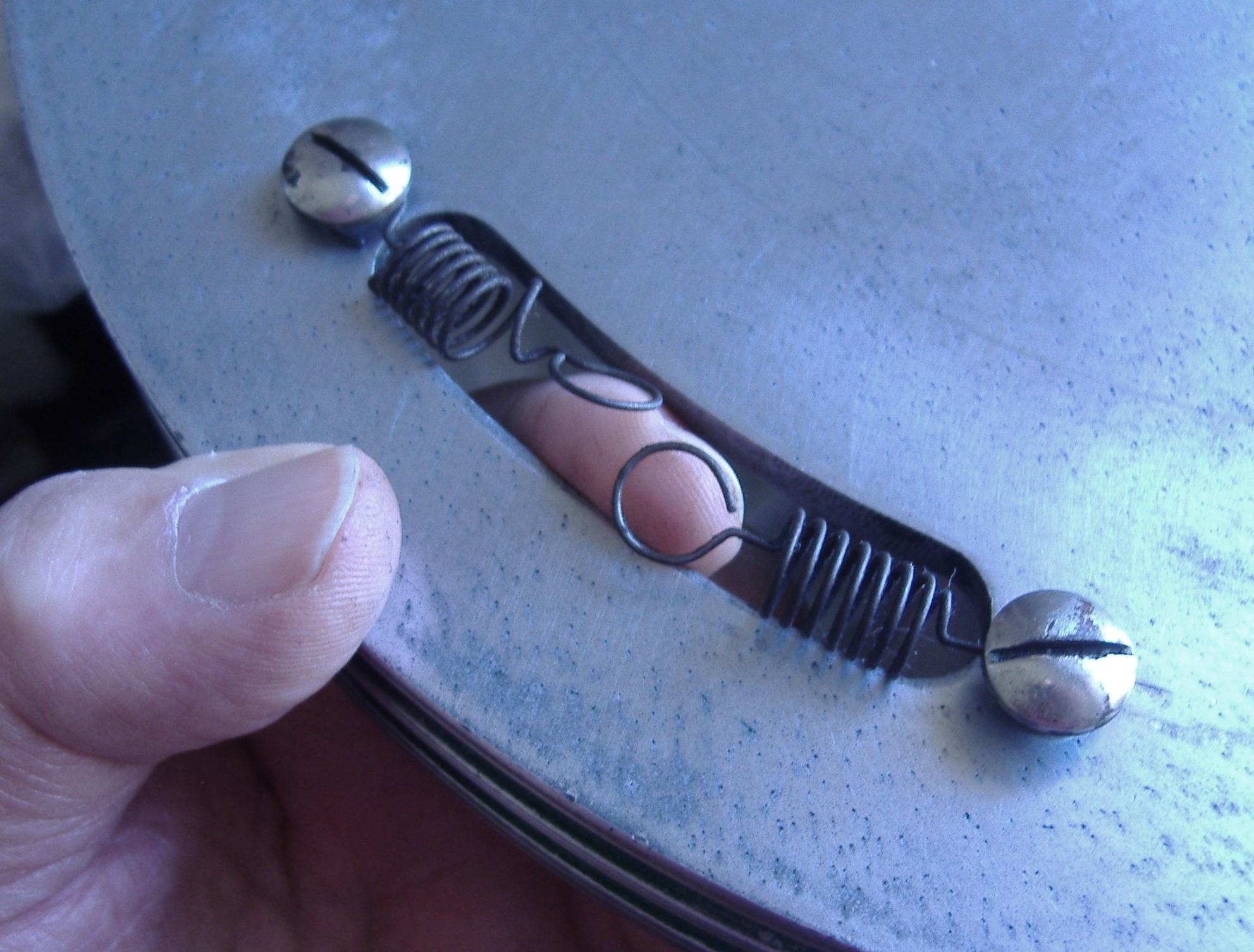
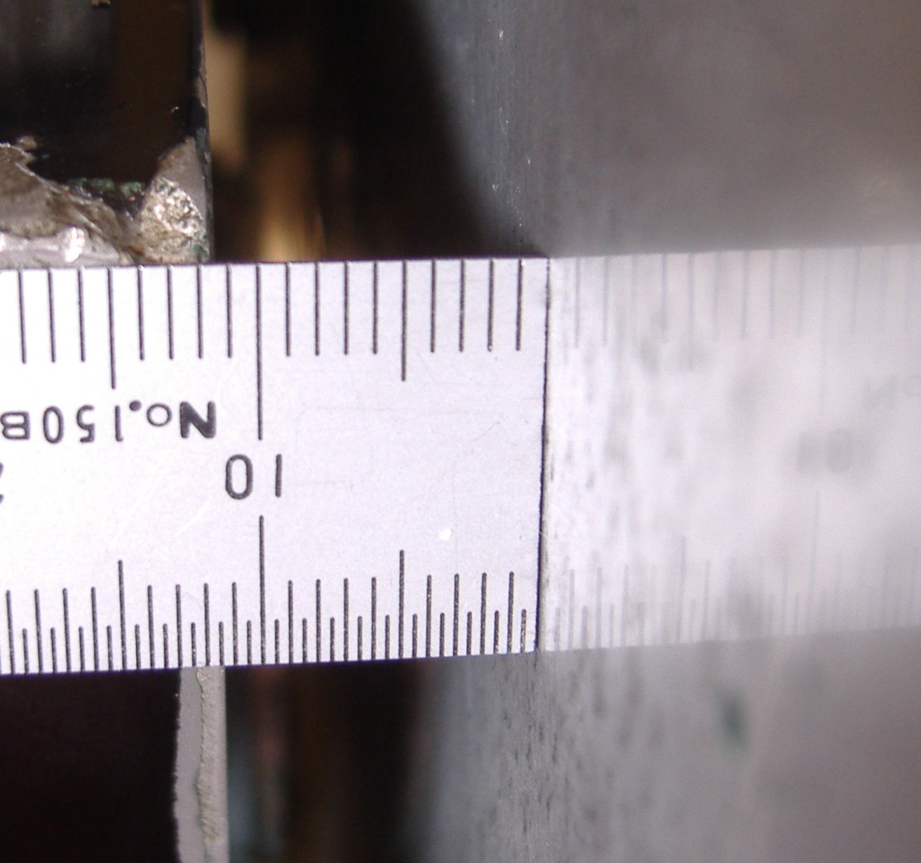
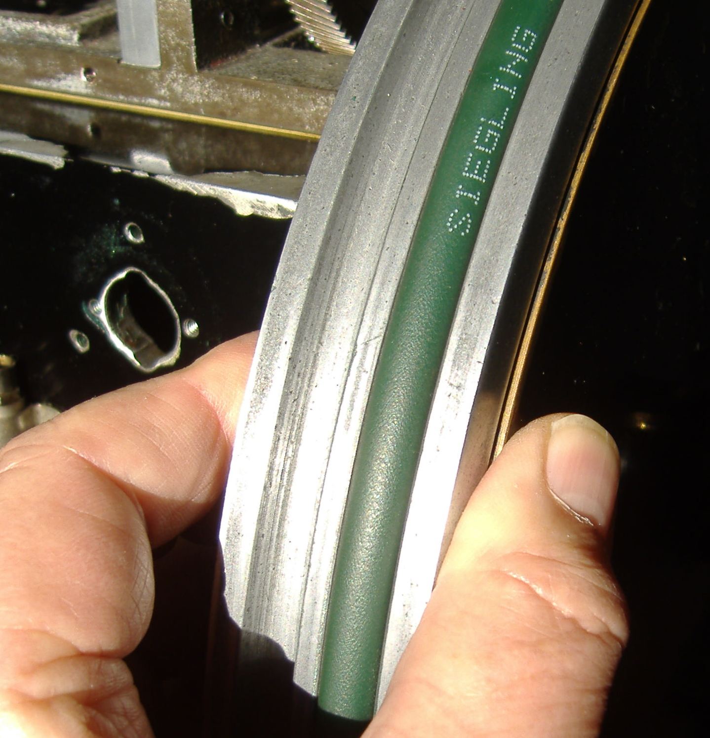
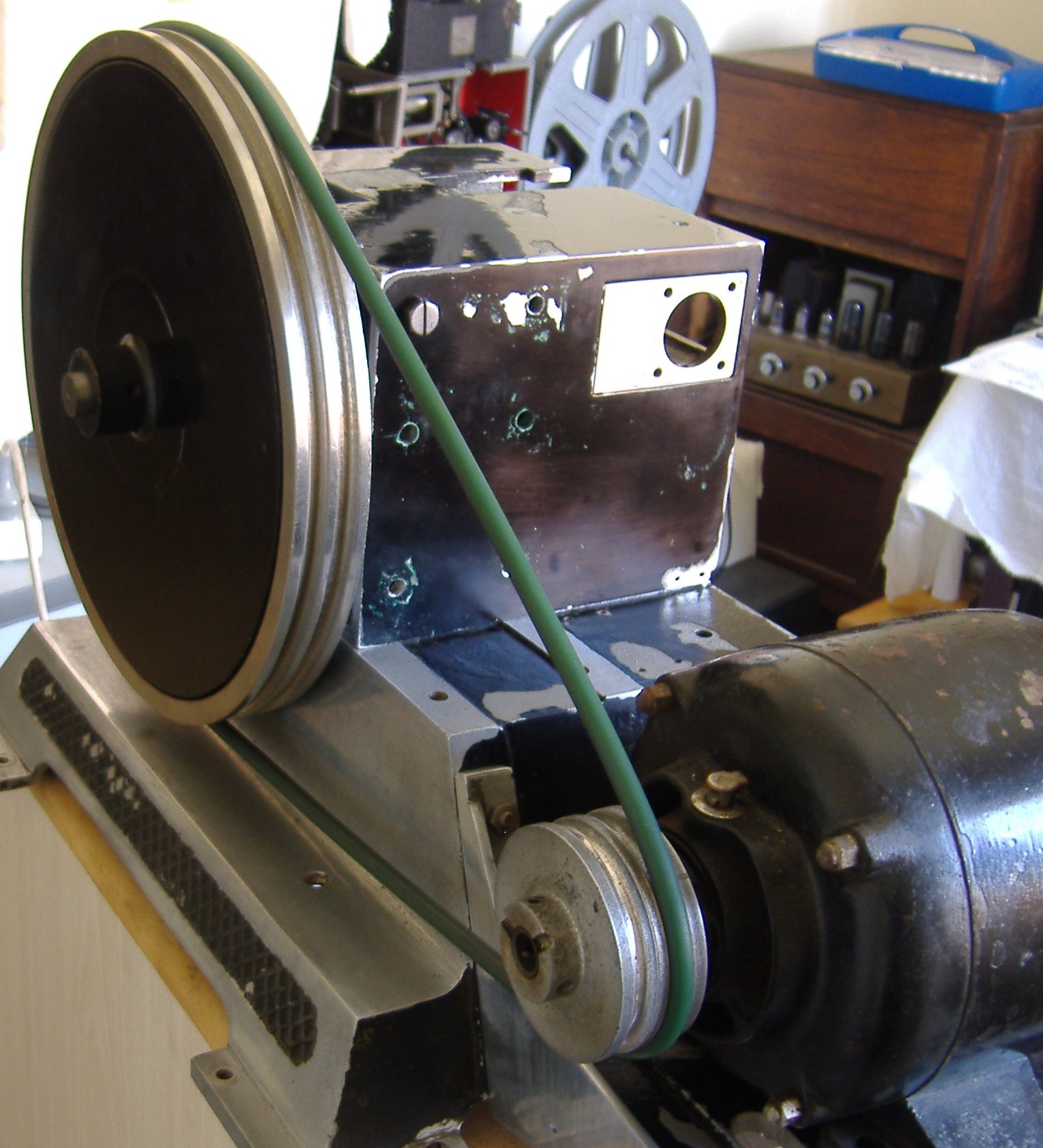
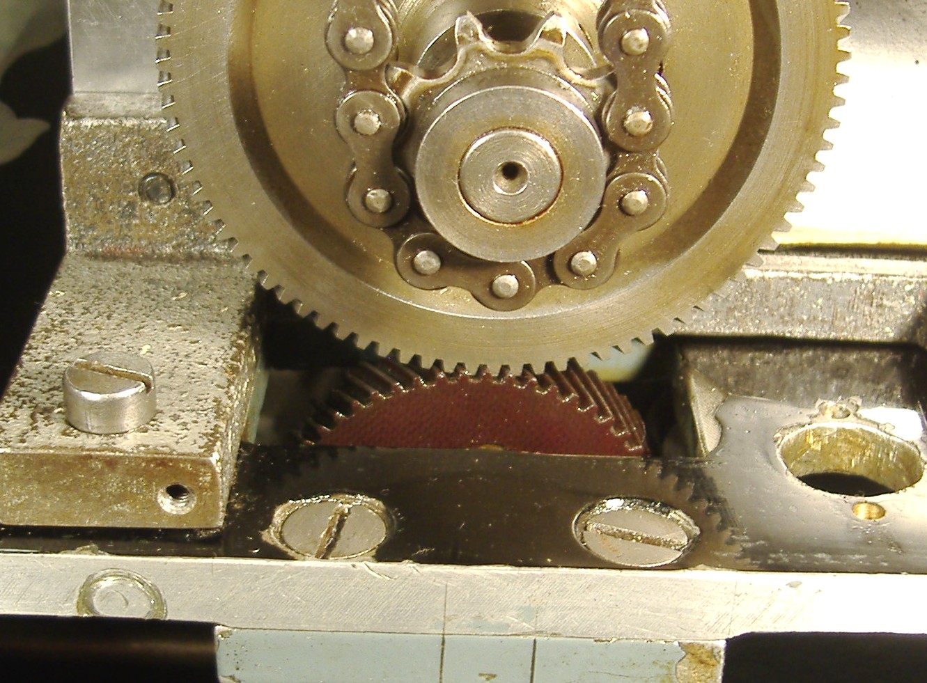
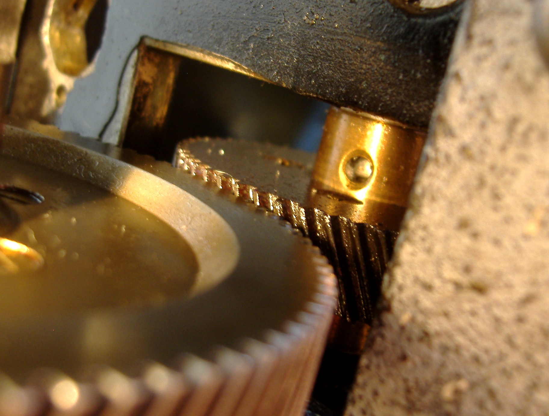
C&W P5  Raycophone Flywheel

The optical tube and holder must be mounted next


The securing screw are on the flywheel side and will be masked by the Flywheel


The shock absorber springs are next


Balance springs in place in the Driven plate


Driven plate ready for mounting onto the sound shaft


Note the slotted keyway which locates the Driven Flywheel


The alignment is gauged by edge of the Driven Shaft bearing


the 3 grub screws
The 3 grub screws are tightened up allowing a gap of 11mm between the sound head body and the Driven Flywheel to prevent the balance springs contacting the body of the Sound Head


the 3 2

A chinagraph pencil marks the position of the keyway on the very heavy Flywheel


The locating pin is shown through the Driven Plate


This leaves about 5 mm of the sound shaft showing


this leaves2
This leaves about a 1 mm edge between the two flywheel segments


The three grub screws are tightened firmly


The Balance springs are lifted onto the pegs


balance 2


balance 3


balance 4


balance 5


balance 6


balance 7


balance 8


balance 9


balance 10


balance 11

Carefully lift the projector head on to the base
Carefully lift the projector head on to the


The all important joint between the sound head an the projector spend time over the gear meshing of the fibre gear and the steel projector driving gear


Insert shim under the frame as required
Insert shim under the frame as required; gently rotate the two gears in meshing checking for tightness “not too lose and not to tight” spend time on this


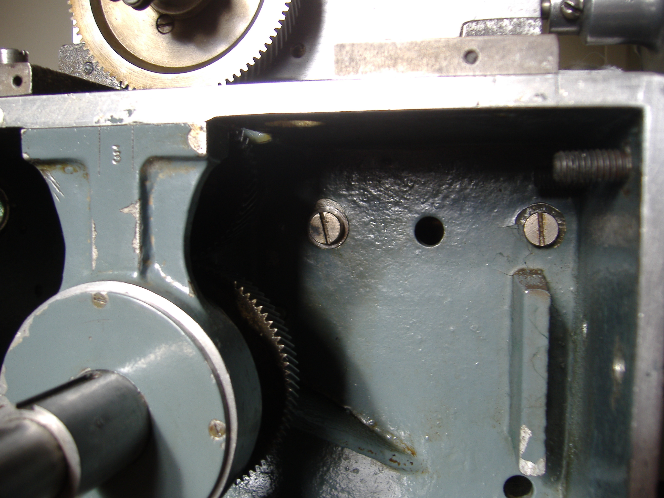
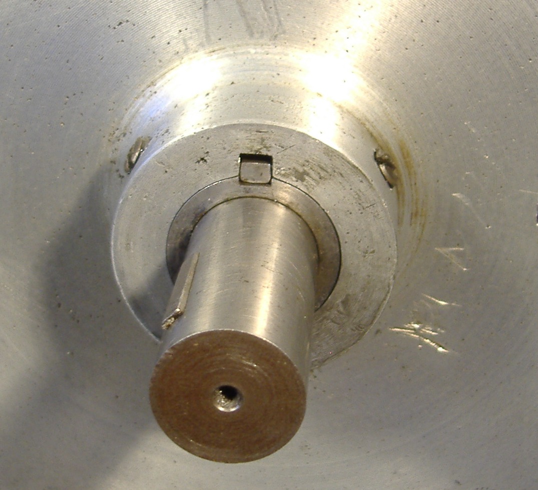
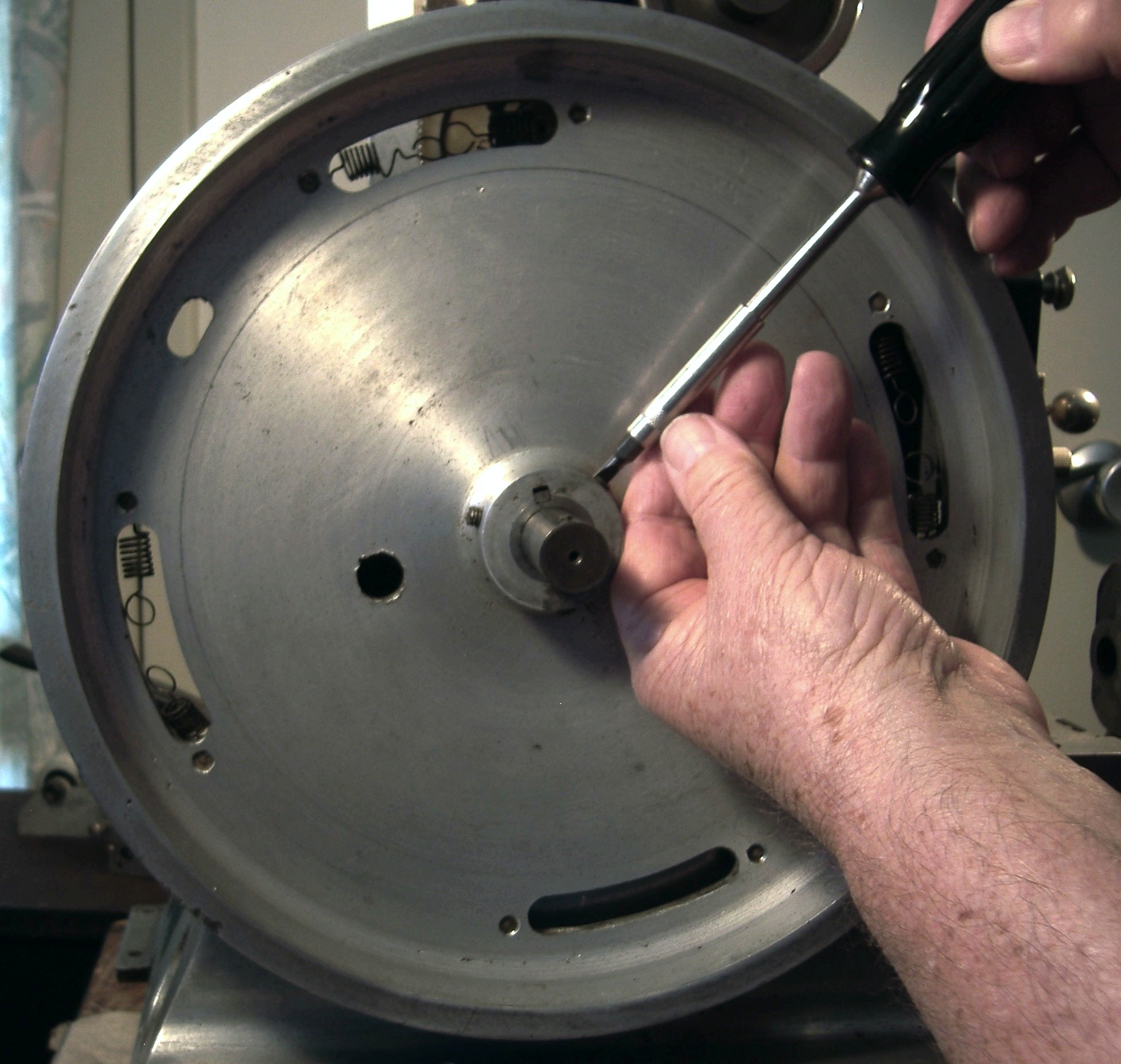
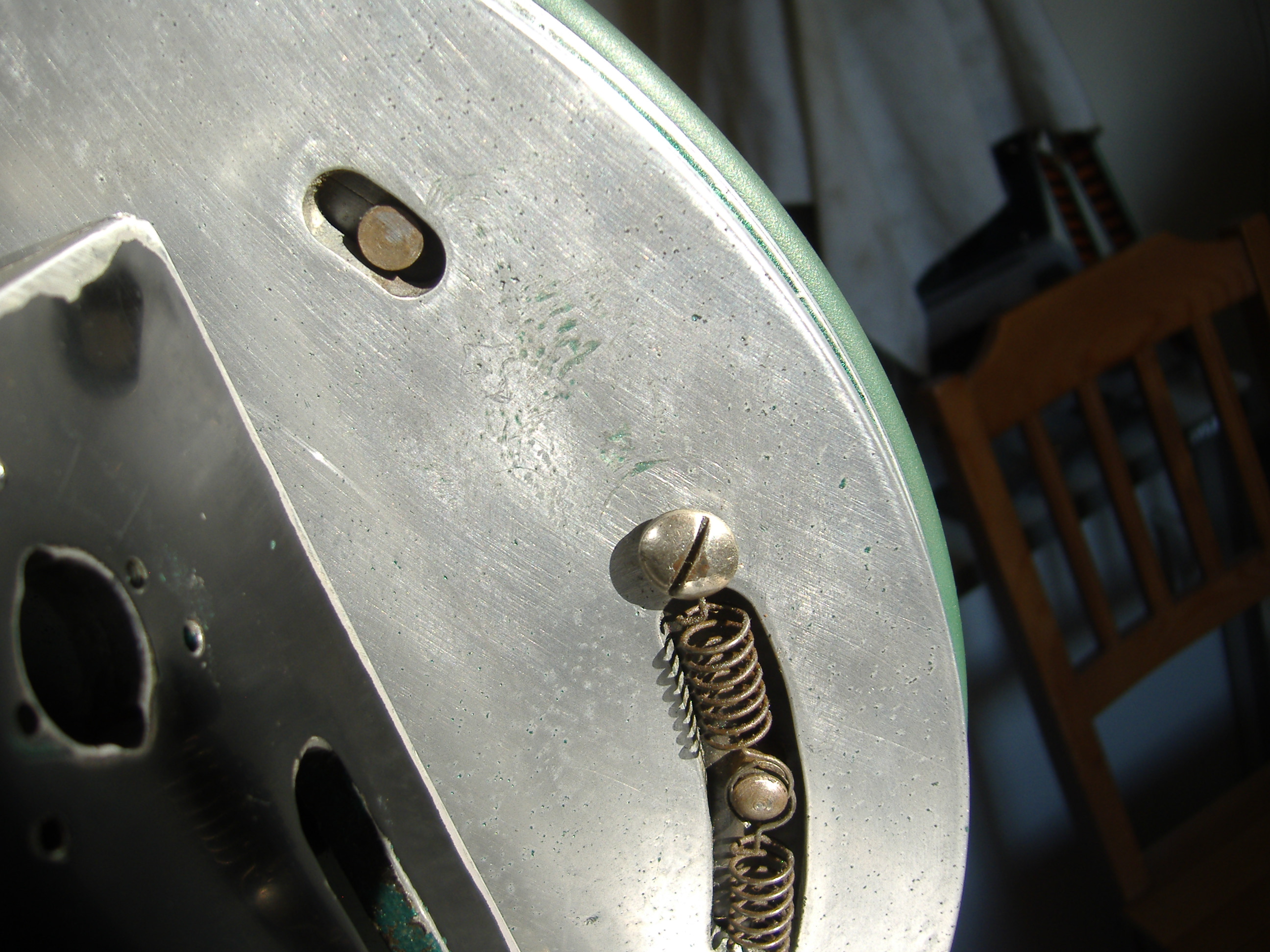
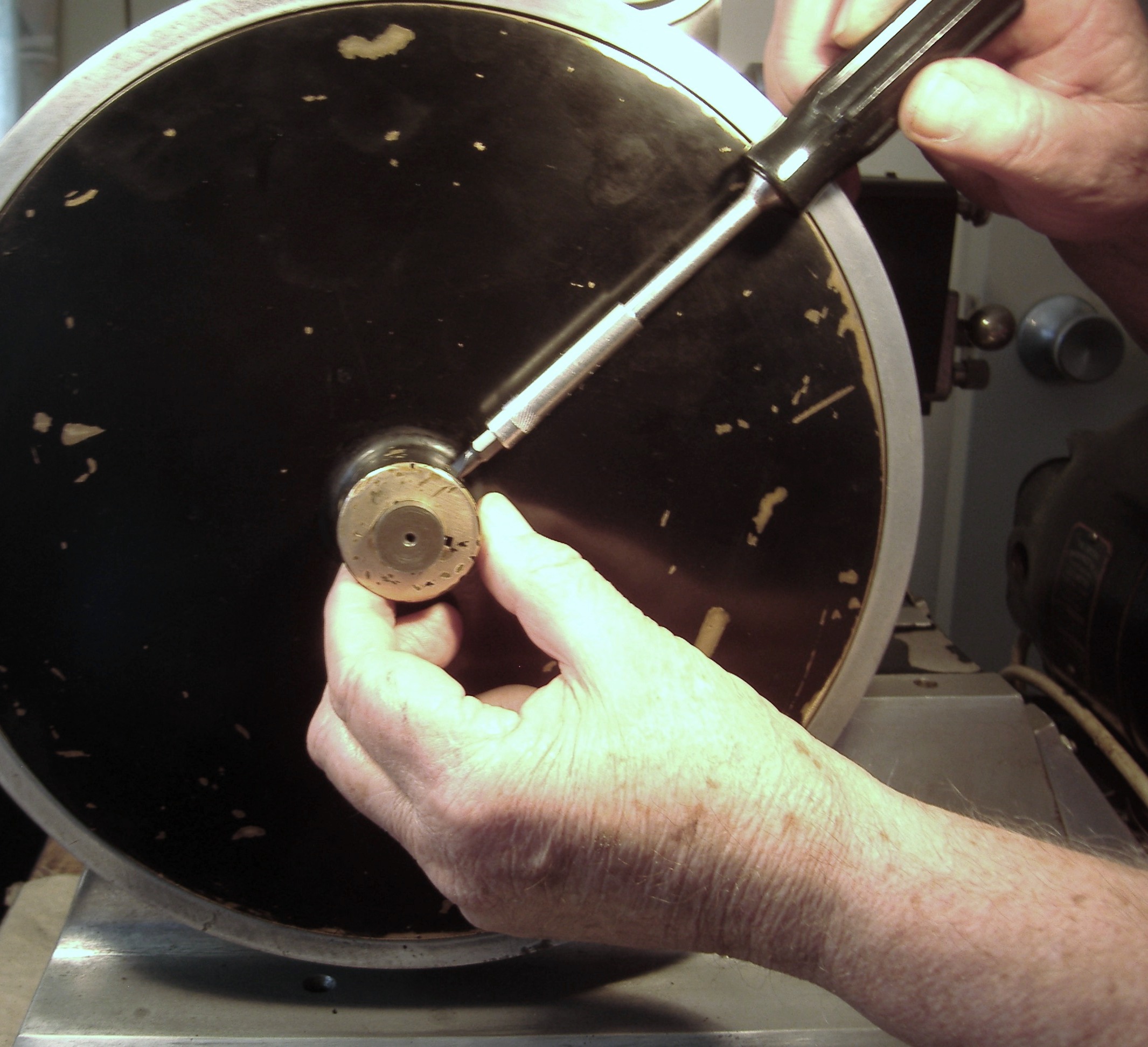
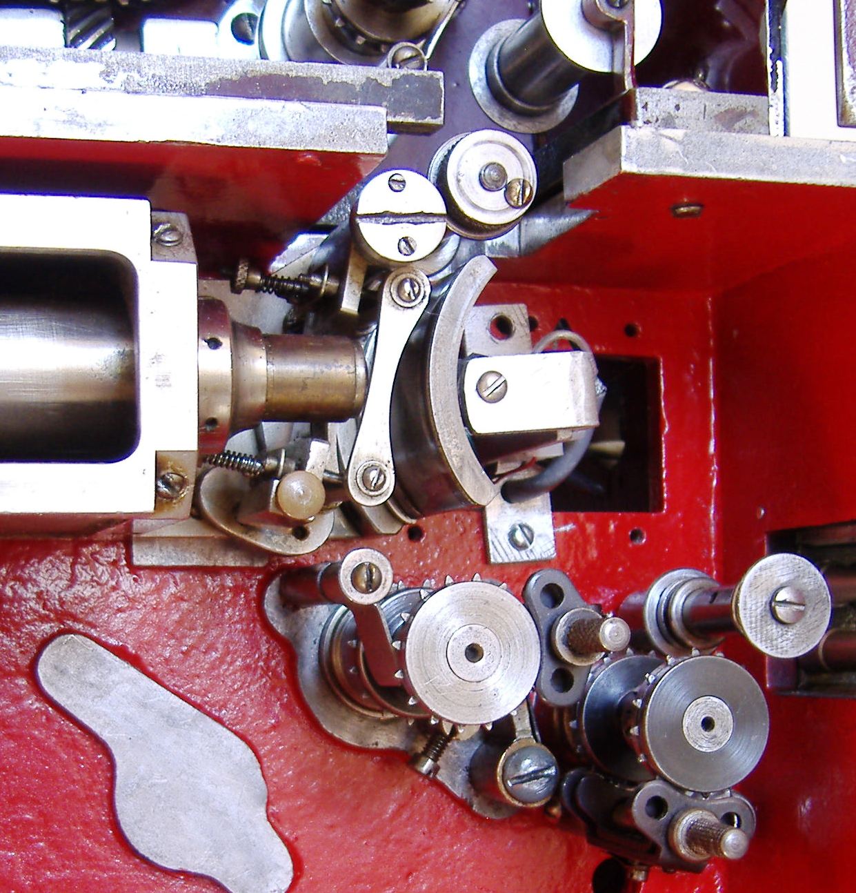
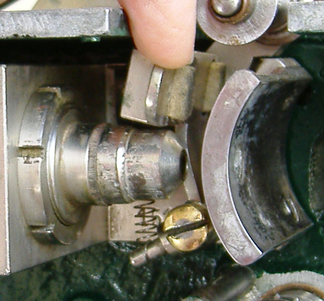
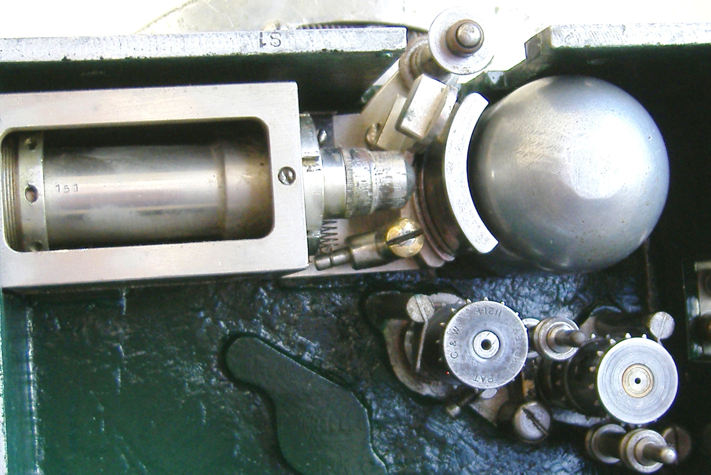
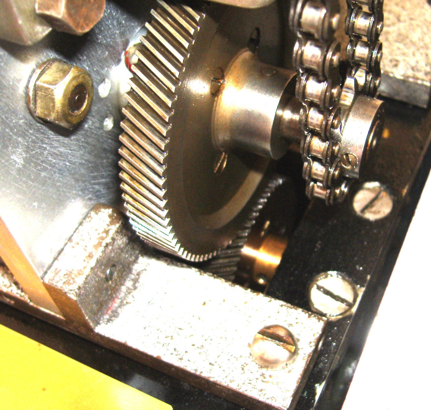
Insert fixing screws just nip them up and check the messing again by carefully rotating the flywheel in a forward direction

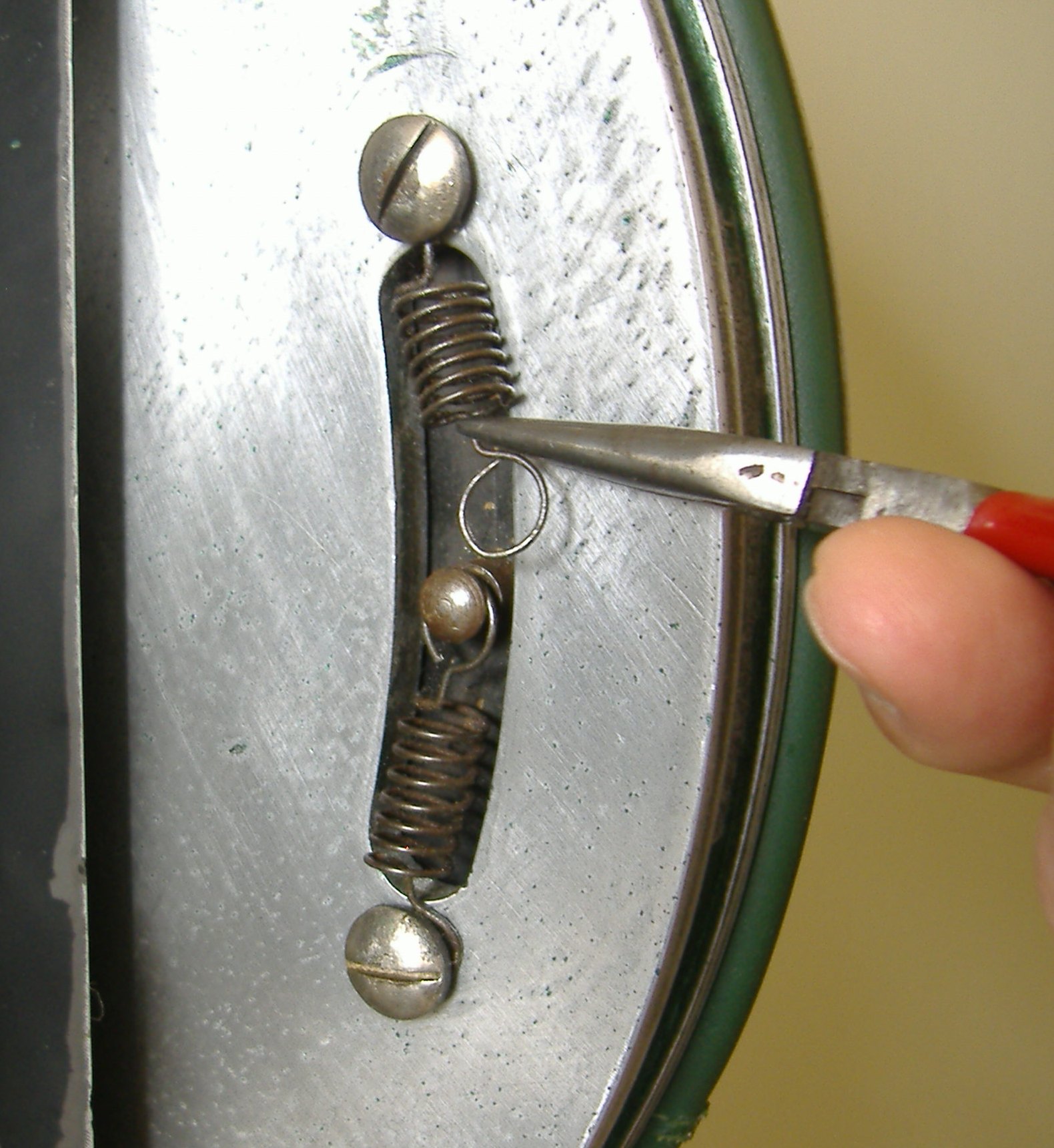
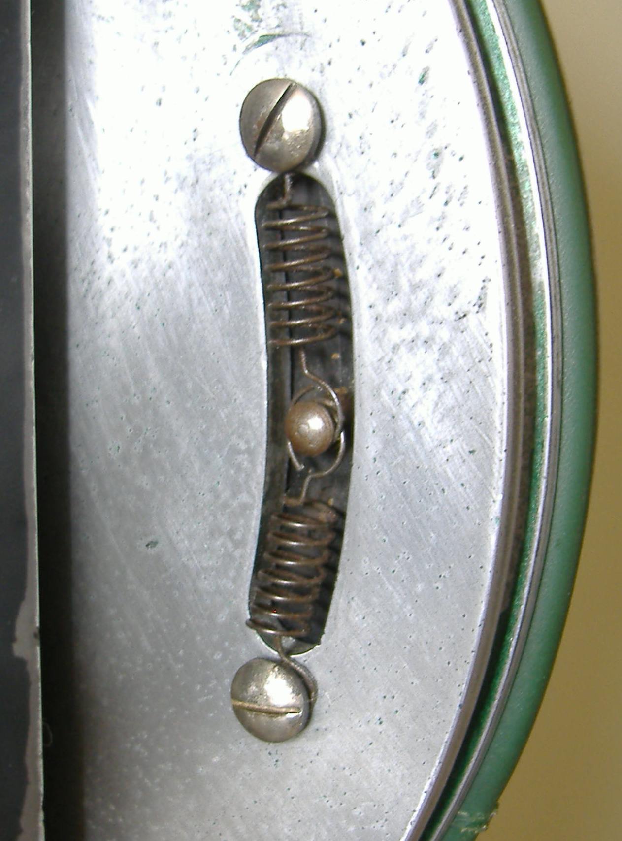
If all’s well tighten up the mounting crews

One drop of oil to the often forgotten fibre gear oil hole


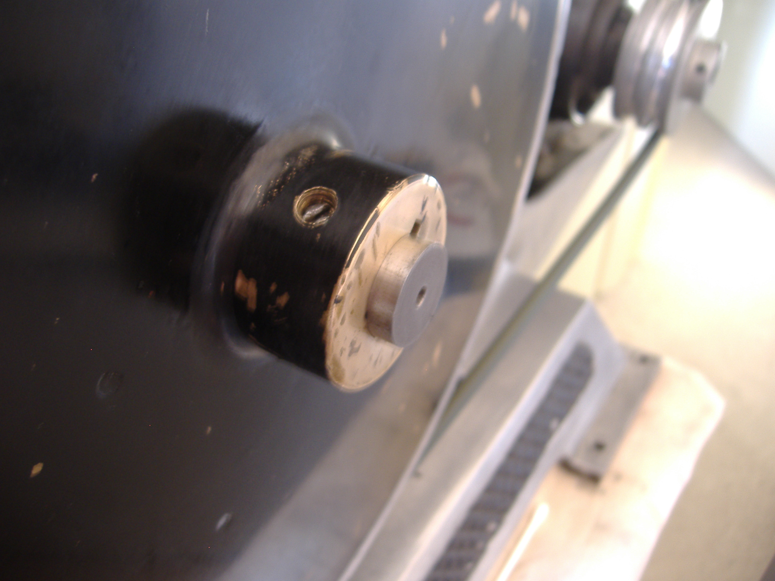
Turn on  the motor switch and let the projector  run have your finger on the switch just in case, listen closely to the sound of the meshing of the gears

A very light fizzing noise? Any more than that investigate, a grinding noise stop!

All’s well !
All’s well !


Scroll to Top