AMMPT (The Australian Museum of Motion Pictures & Television Inc.) AMMPT Western Region (Inc.)trading as Pictures In Motion
Assembling Cumming & Wilson Projectors E and D
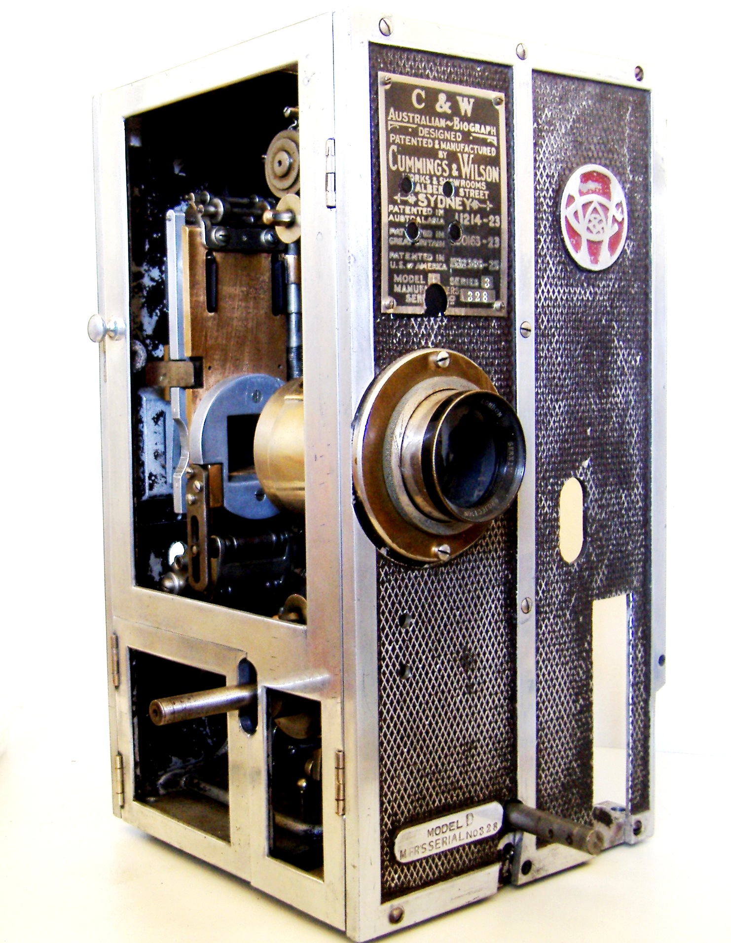
Assembling Cumming & Wilson Model E No. 502 and Model D No. 328
Richard Ashton
C&W Model D 328 in the original but faded maroon casing colour
The next pictures show the assembly of both these machines but in essence they are both the same construction, showing only minor differences, those being of course that the model E had a rear shutter when it was made. And the model D was retrofitted to a rear shutter operation.
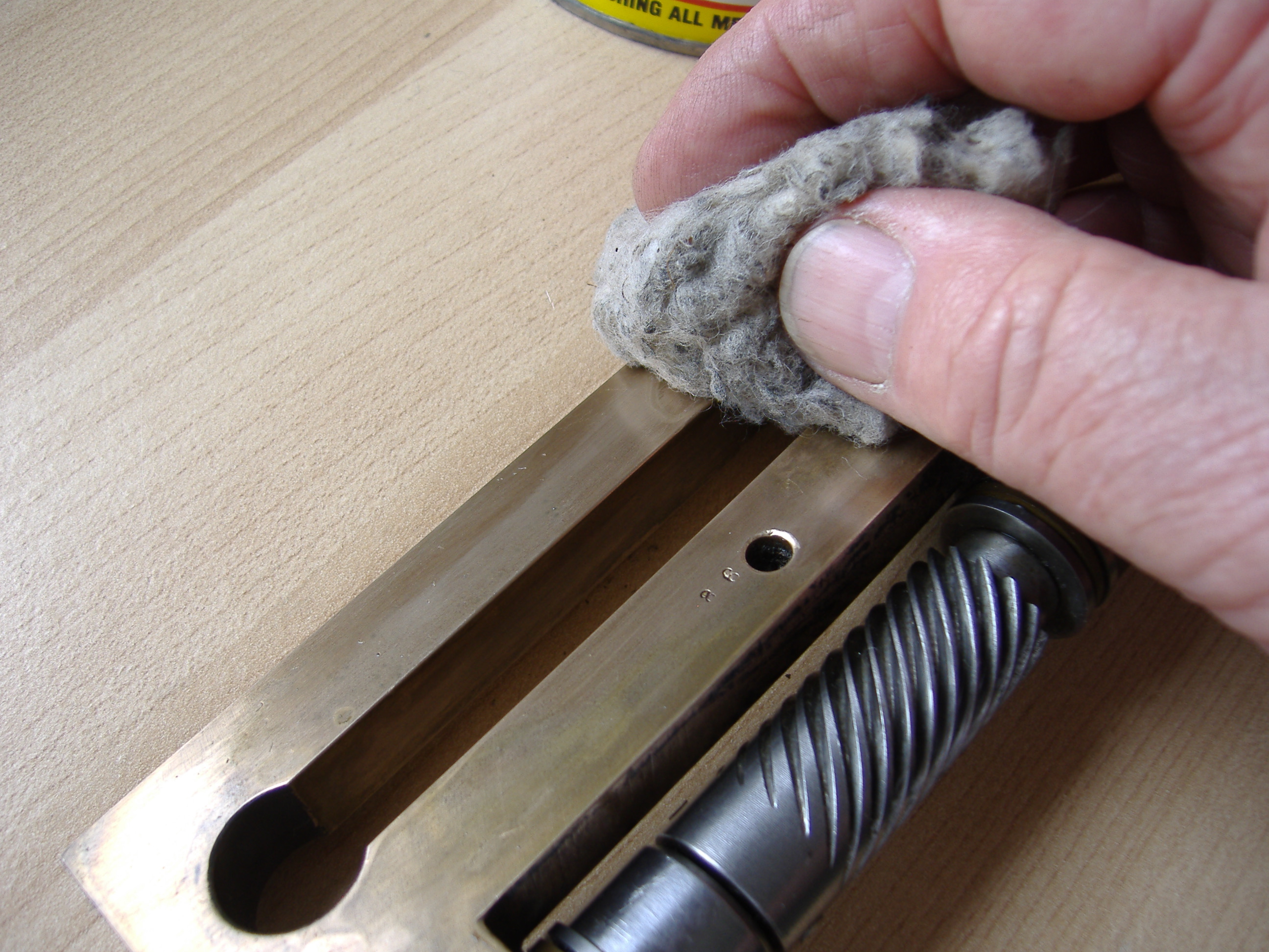
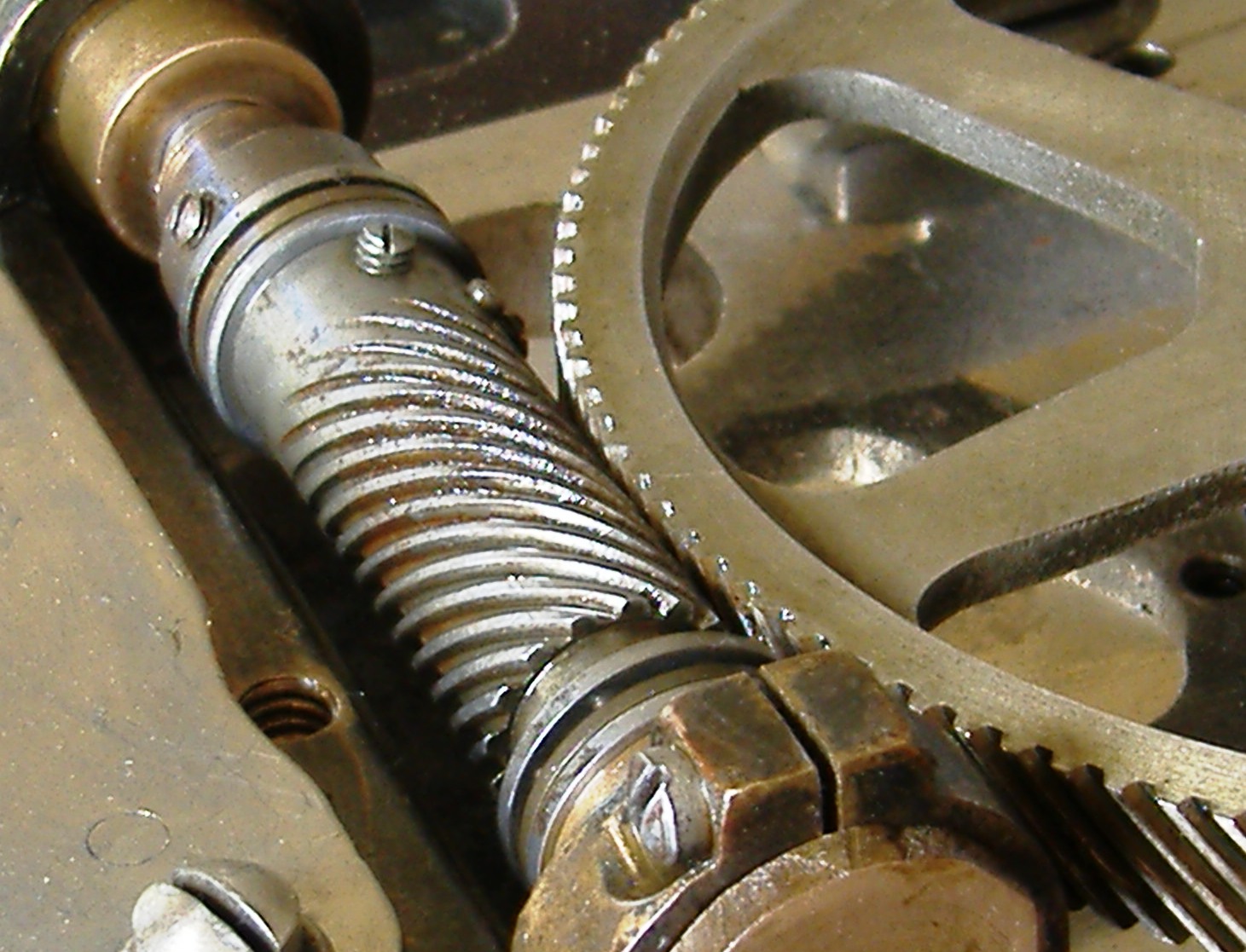
The first set of pictures shows the cleaning up of various elements of the shutter shaft.
The second part shows the assembly of the main plate and sliders fitted to the mainframe
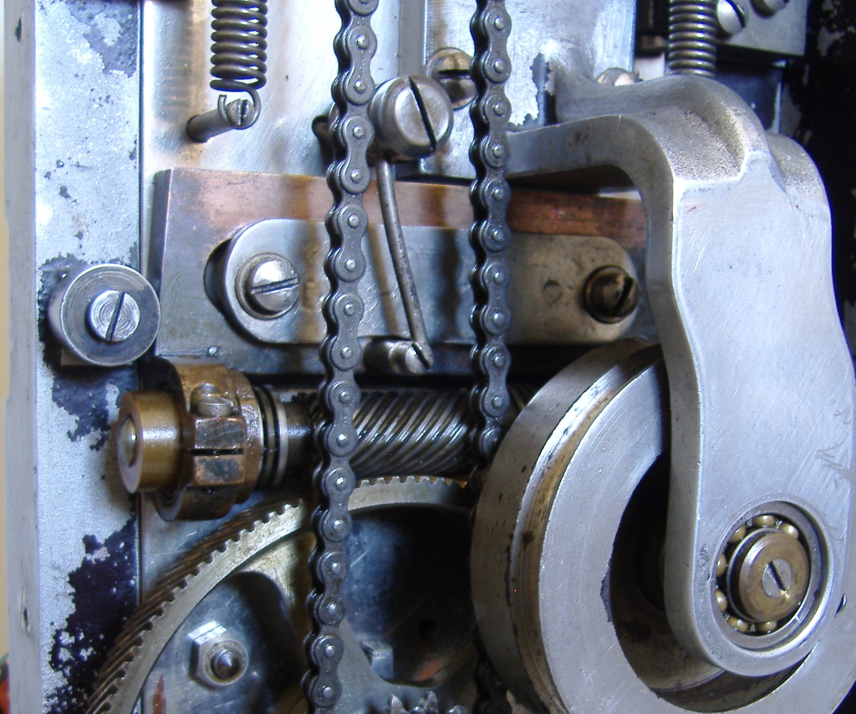
The next part shows the installation of the ball bearing driven shafts this is followed by the main driving gear being installed.
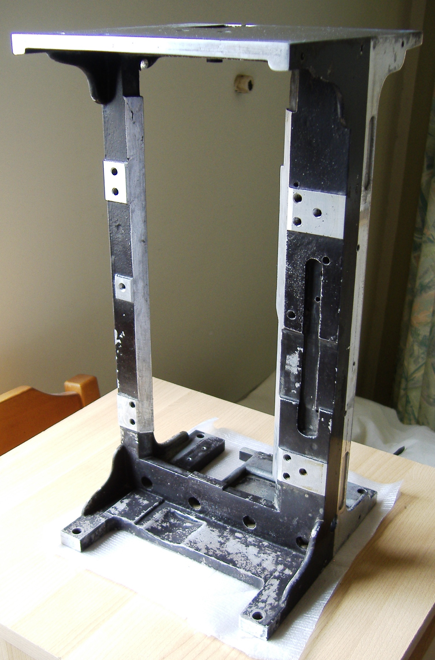
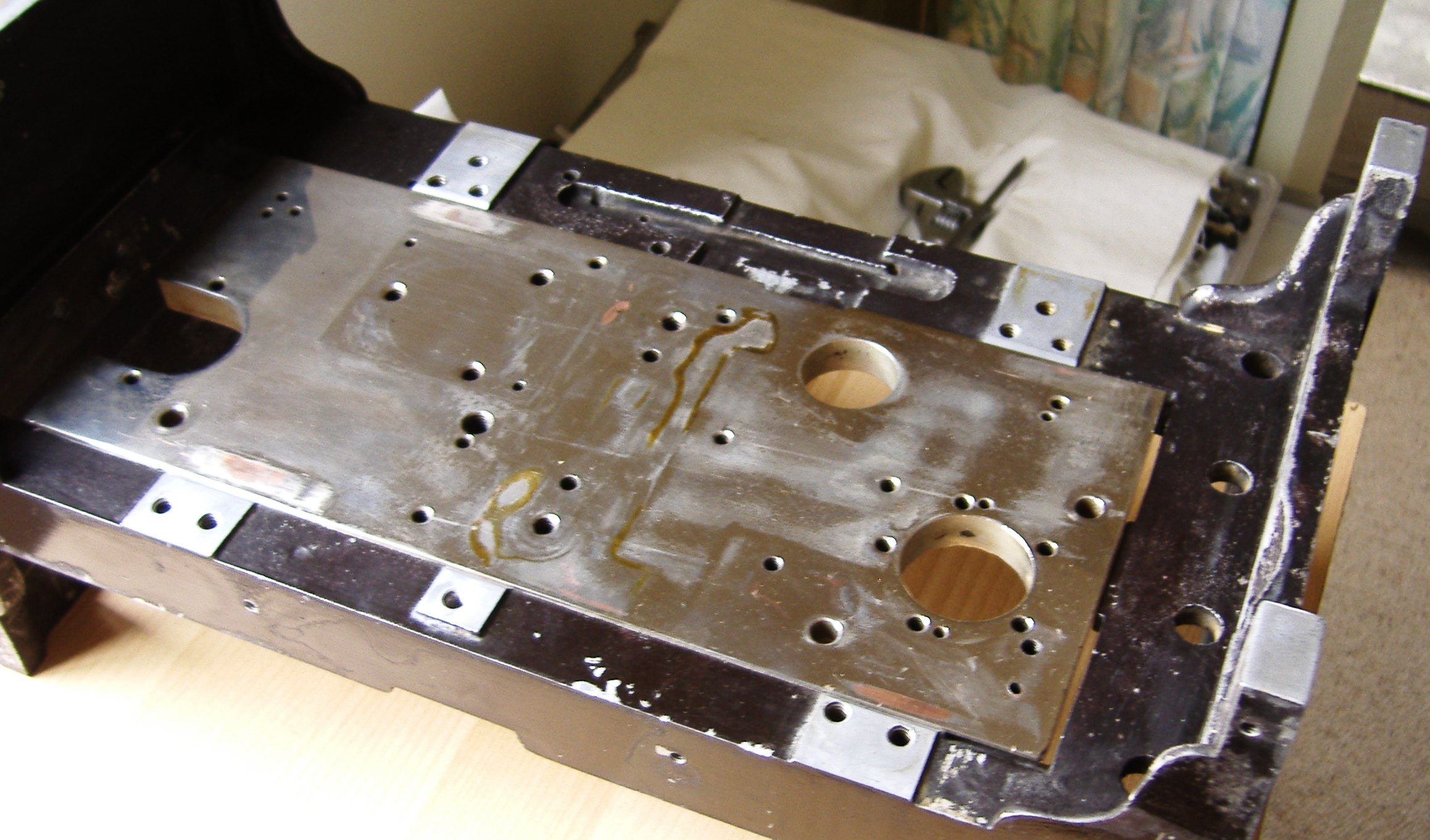
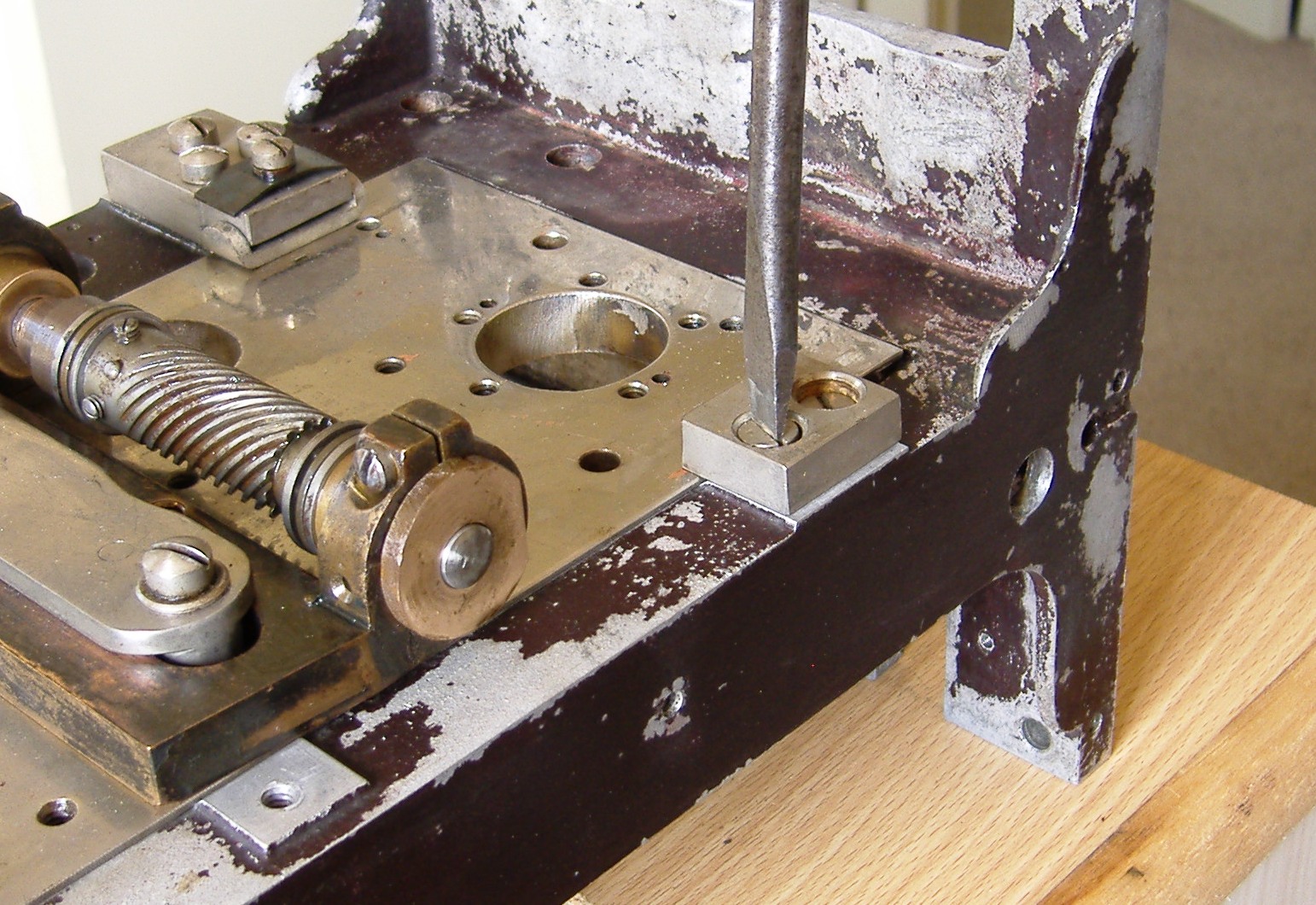
The main frame cleaned up ready to go .
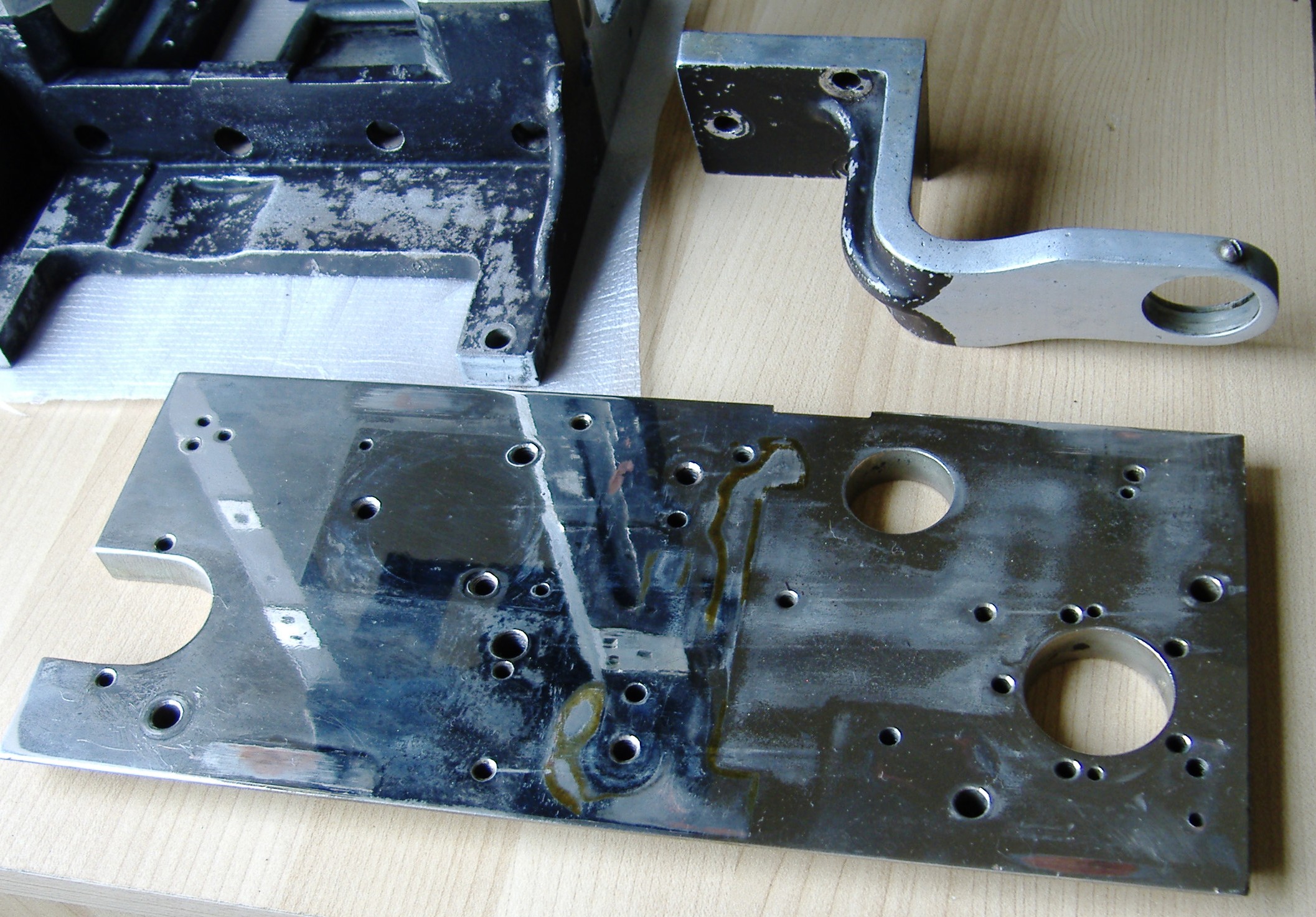
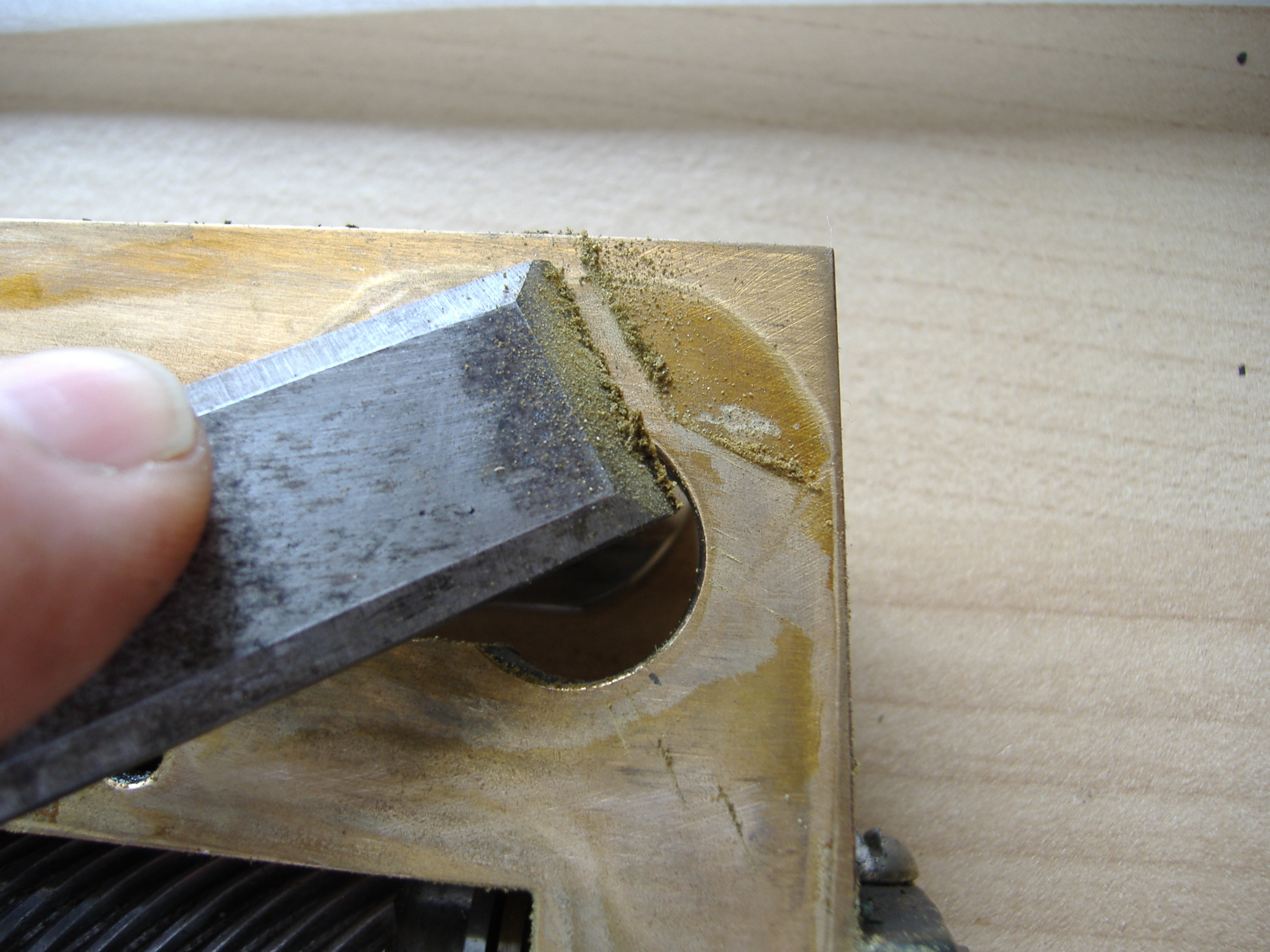
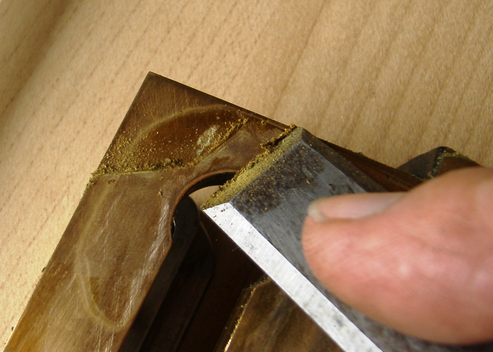
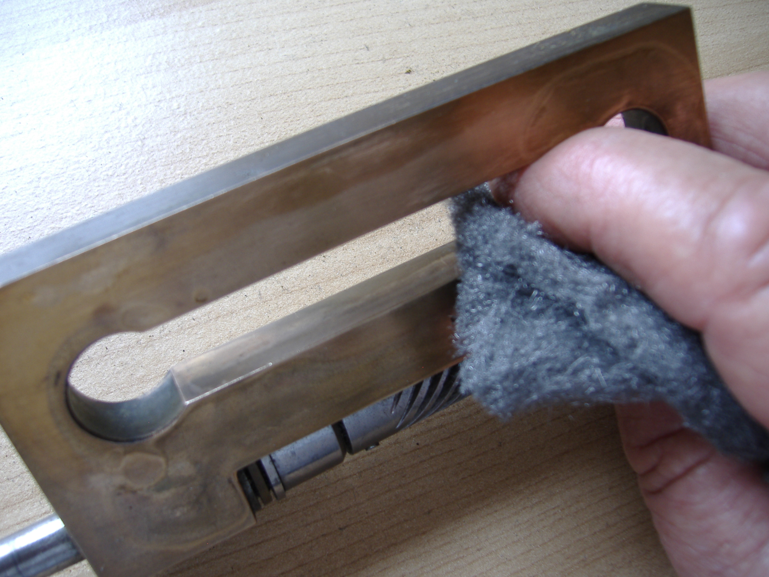
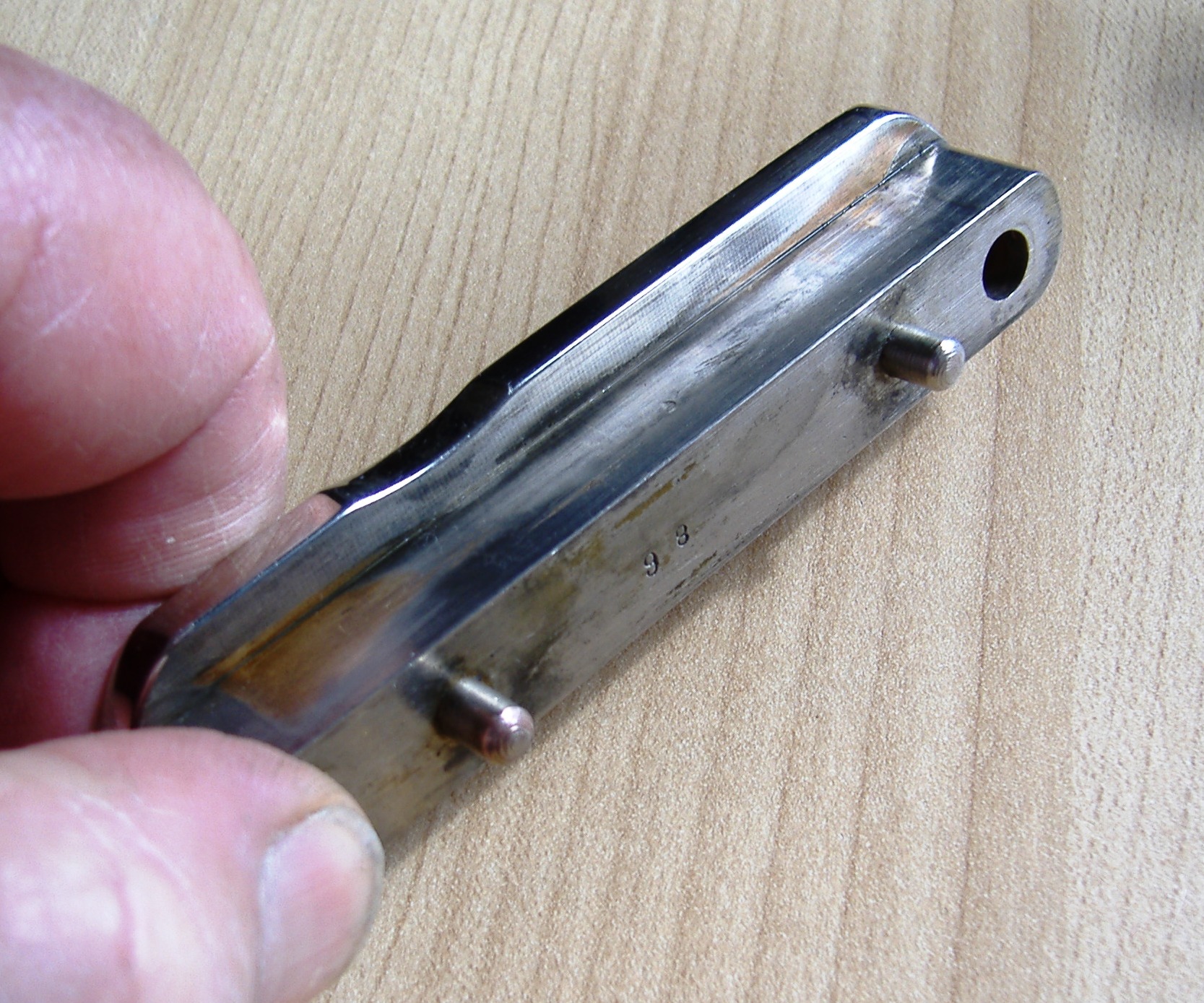
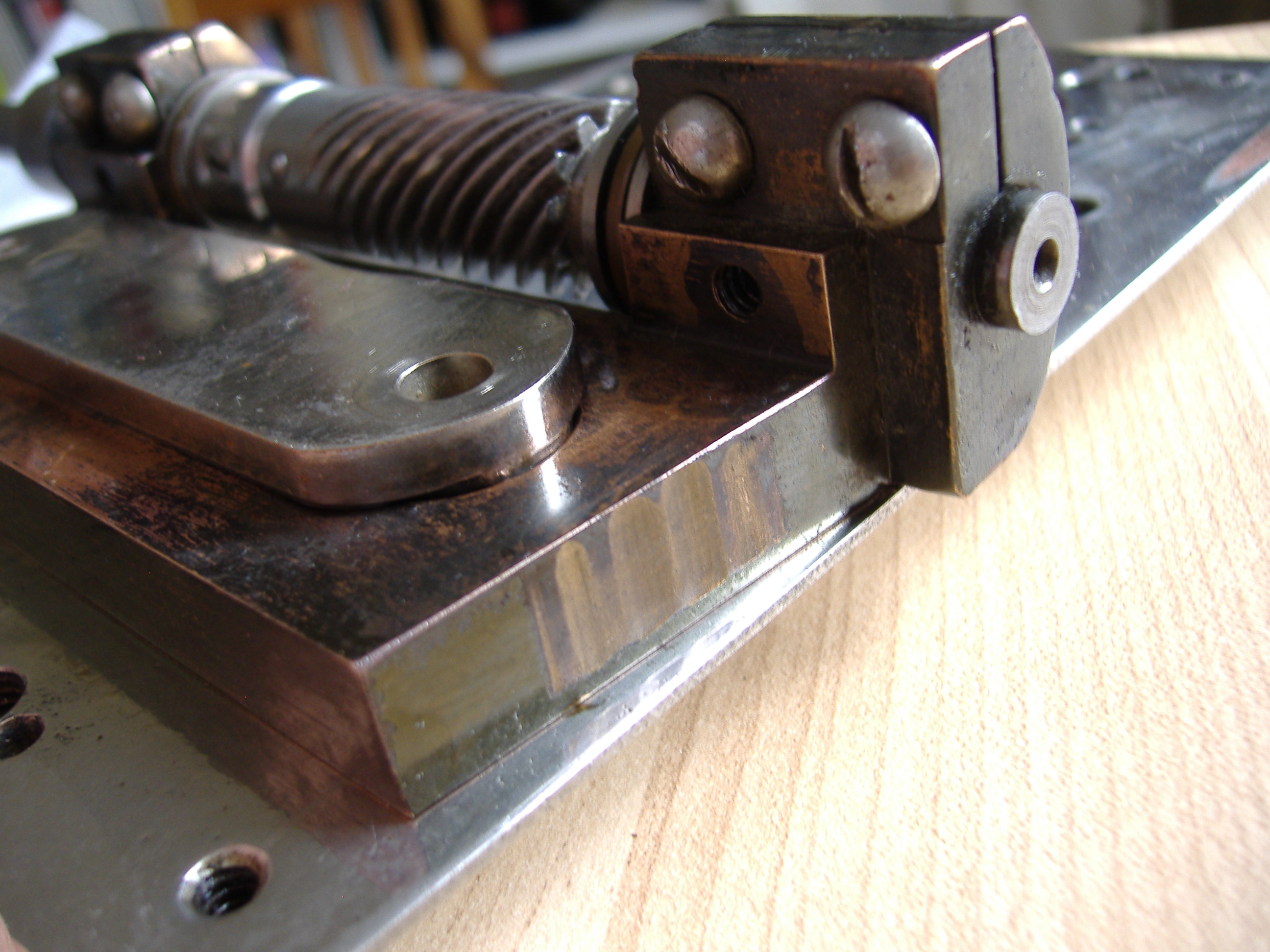
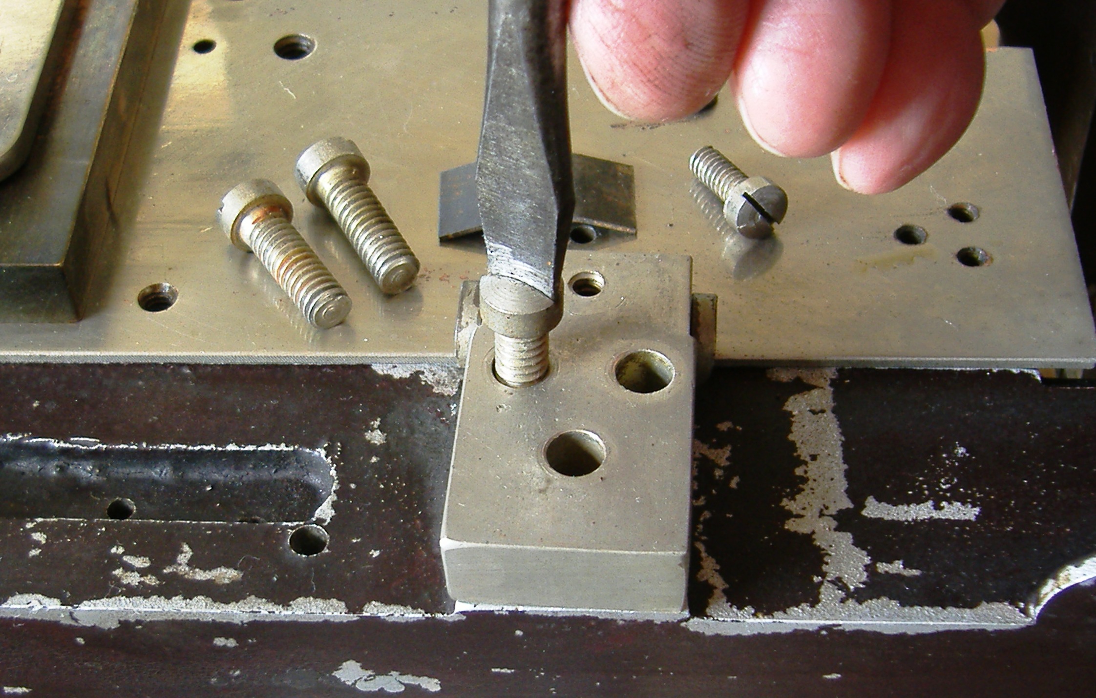
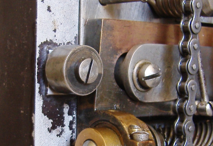
The main plate also cleaned but it shows up scratches and wear marks.The main plate tryout slipped into to the frame.Spindle gear and shutter shaft had a good scrub up, and the ball bearings a spot of oil.The slider spindle holder cleaned up with fine steel wool, but not completely, the baked on oil needed some help.A sharp chisel helped followed by steel wool.The inside of the slider too needed attention.Then PolishSpindle shaft slider securing bracket is also cleaned with steel wool.The machinist pins locate the position on the main plate.
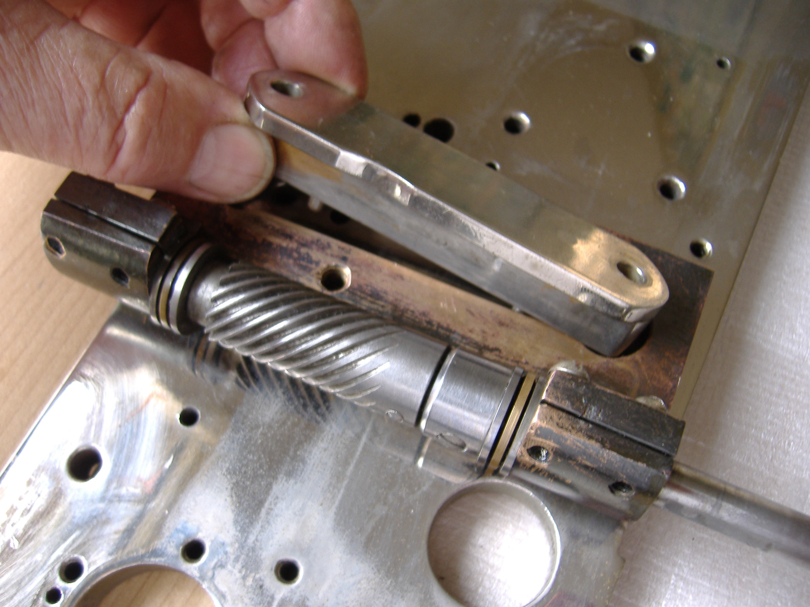
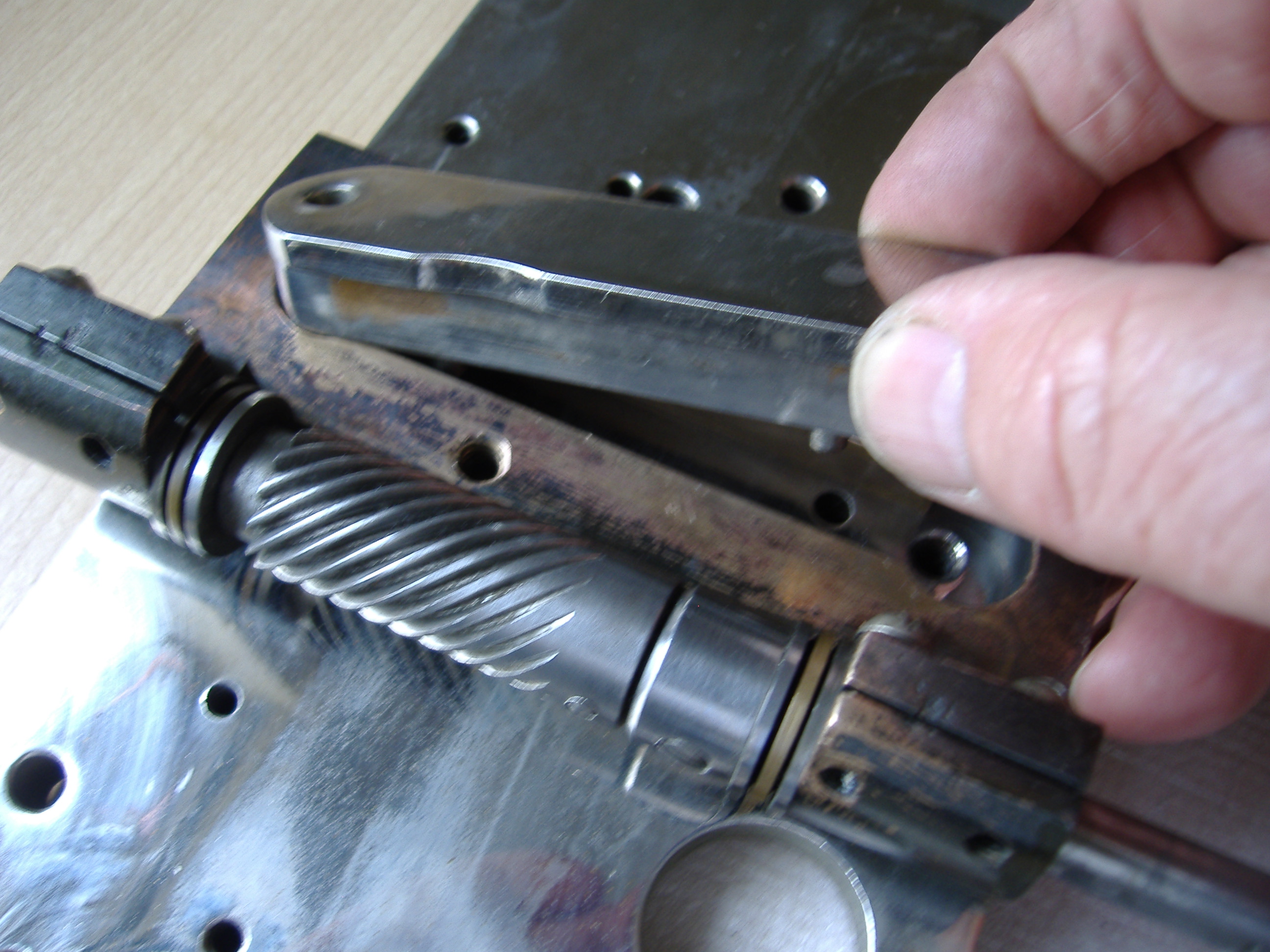
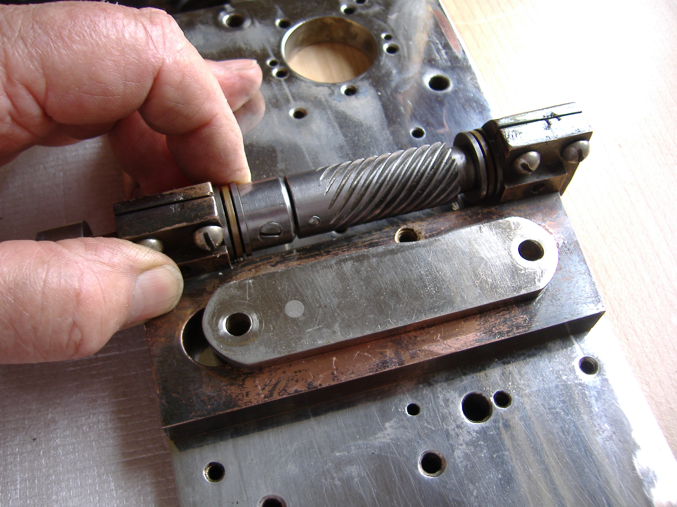
Unusual wear is noticed on the sloping end of the spindle slider.The spindle gear and shaft now slides easily smoothly back and foreword.A trial assembly on the main plate, the two bolts fix the securing plate and the tension spring and securing bolt also now in place, also the spring peg.
For this part of the assembly we switch to C&W Model D No. 328 (c1928)
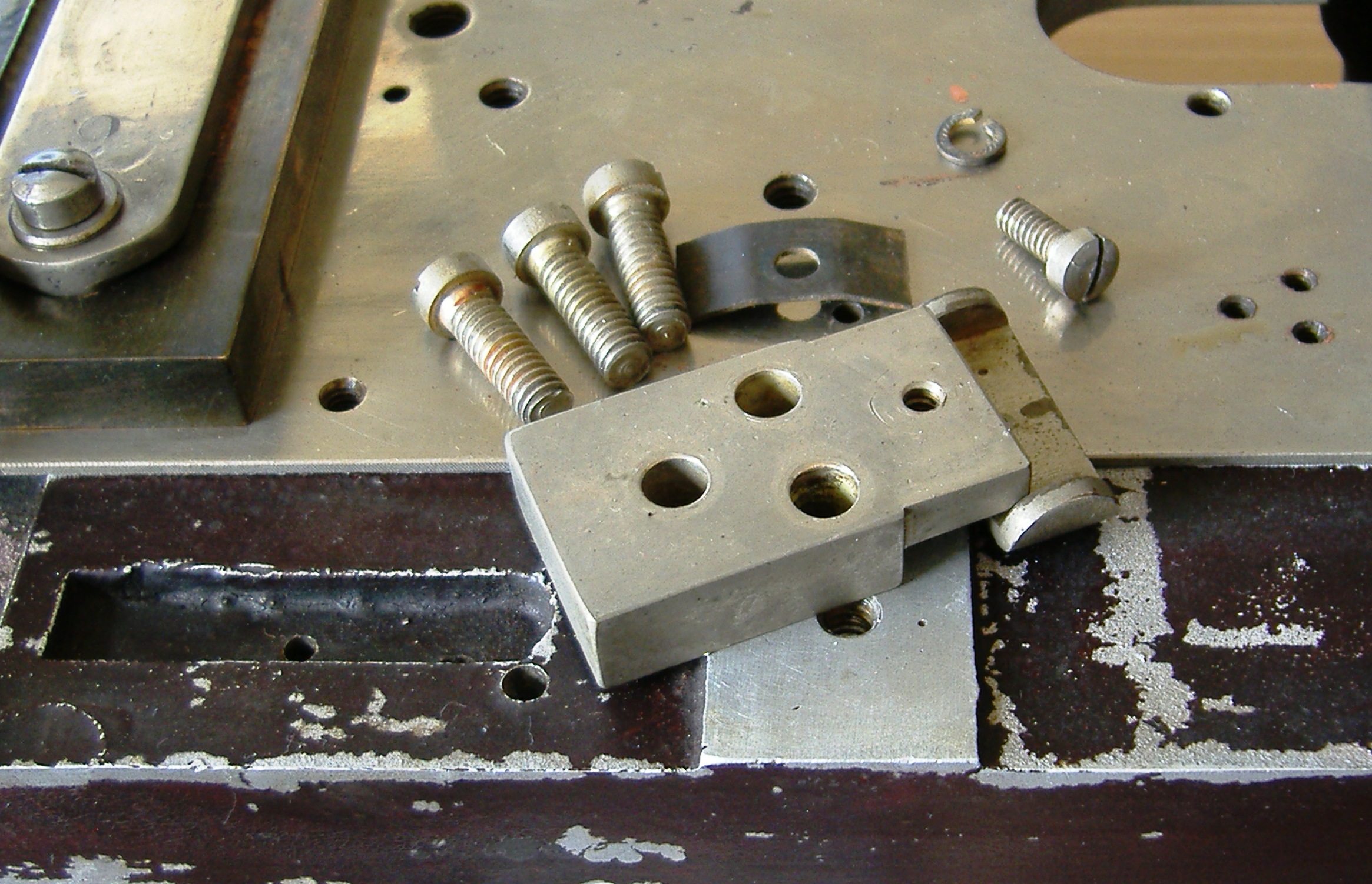
Main plate pressure keeper plates are next, slide under the slide pressure plate
More screws then fix the tension spring.
Then fix the steel tension plates under the back slide guide followed by the tension spring Below: Note they are slightly off centre and only fit one way
Same for the lower slider keeper plateThe one the other side now the fixed keeper top and bottom.
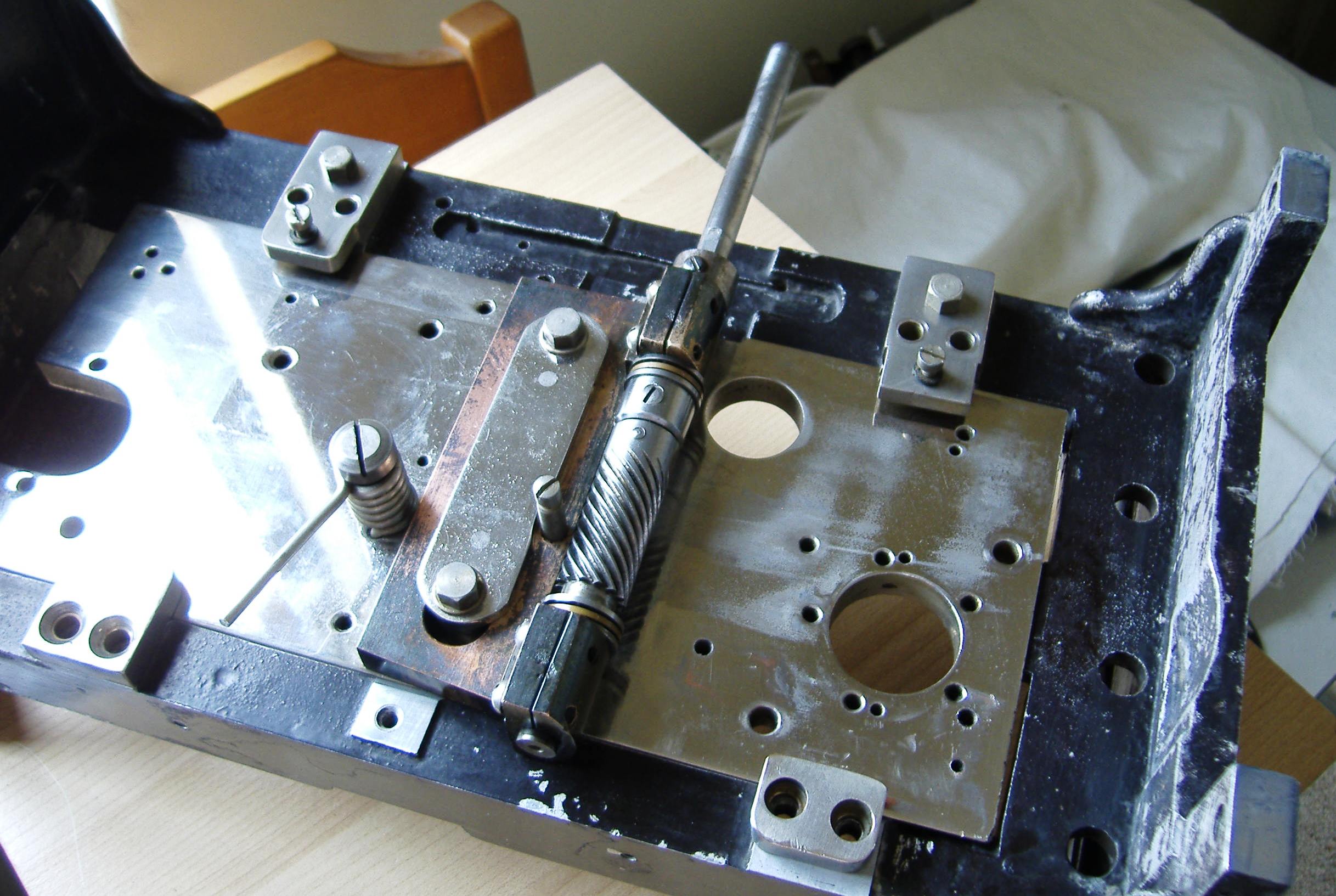
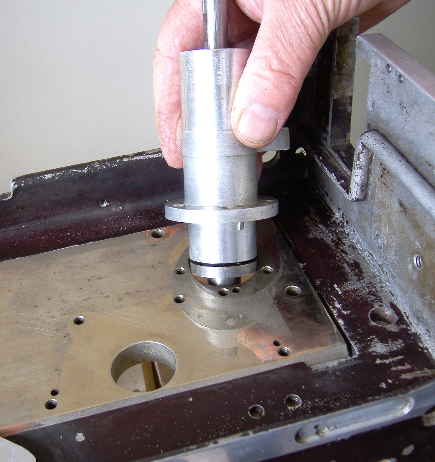
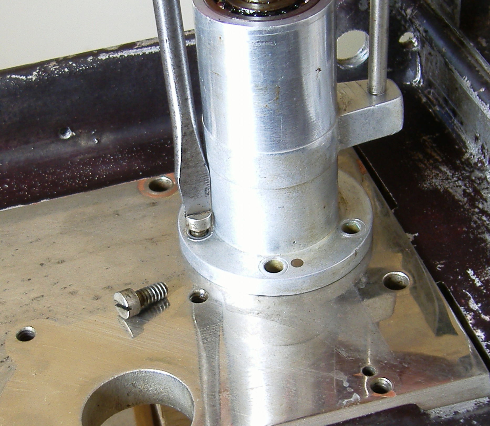
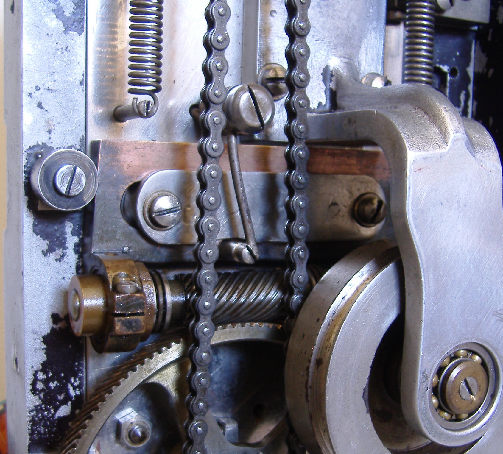
The machinist pins locate the lower feed main bearing, then the 5 holding screws.
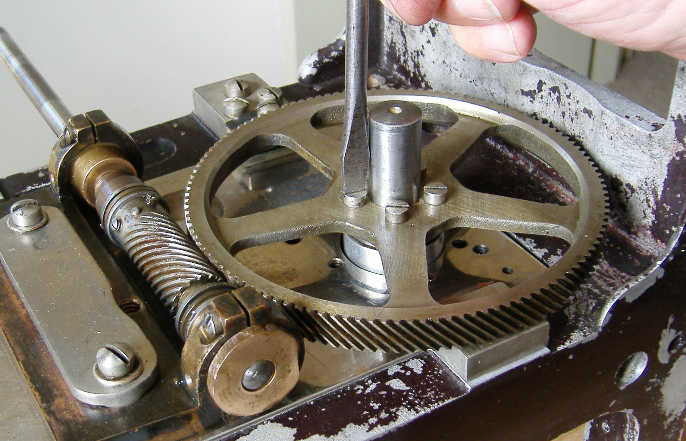
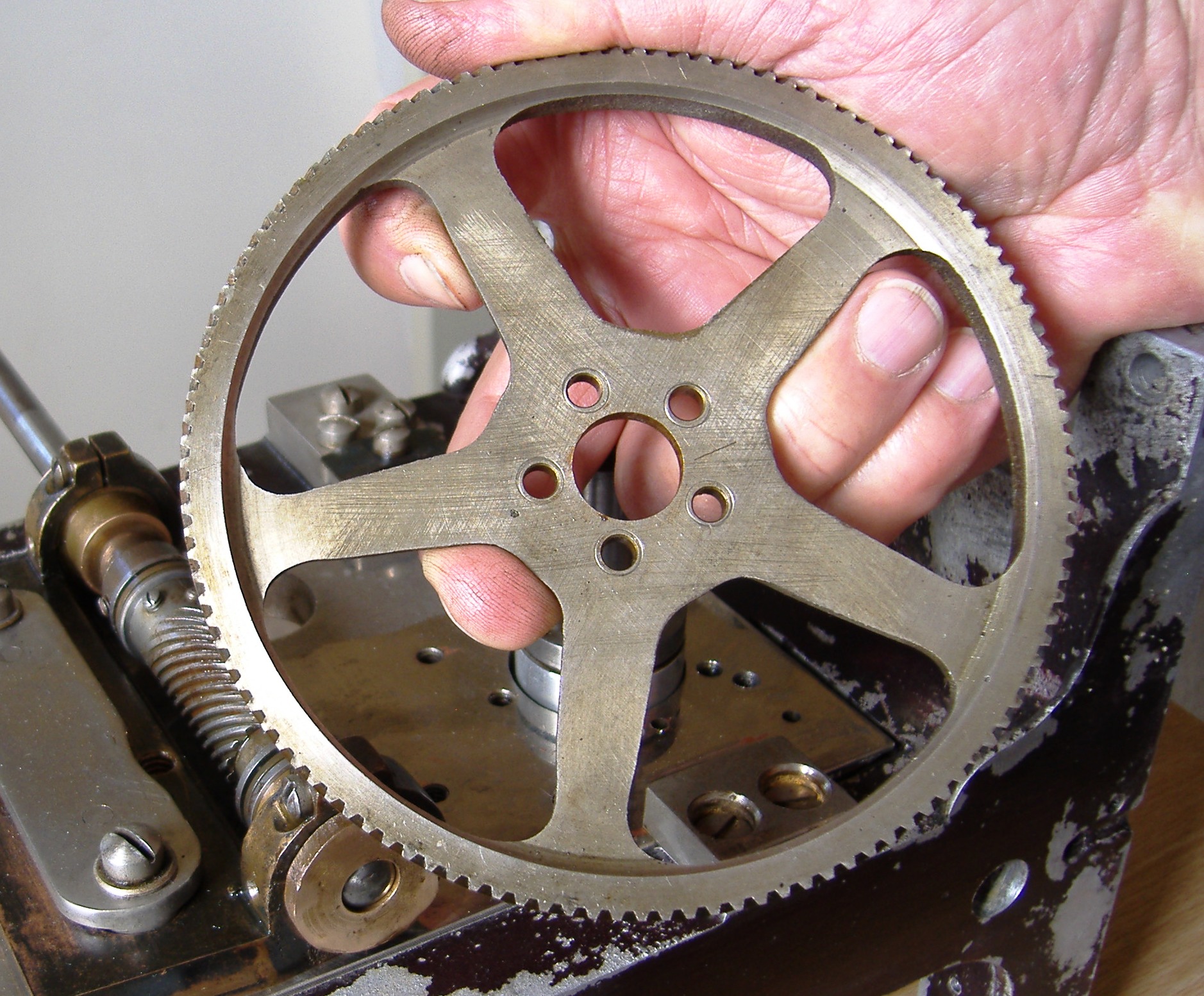
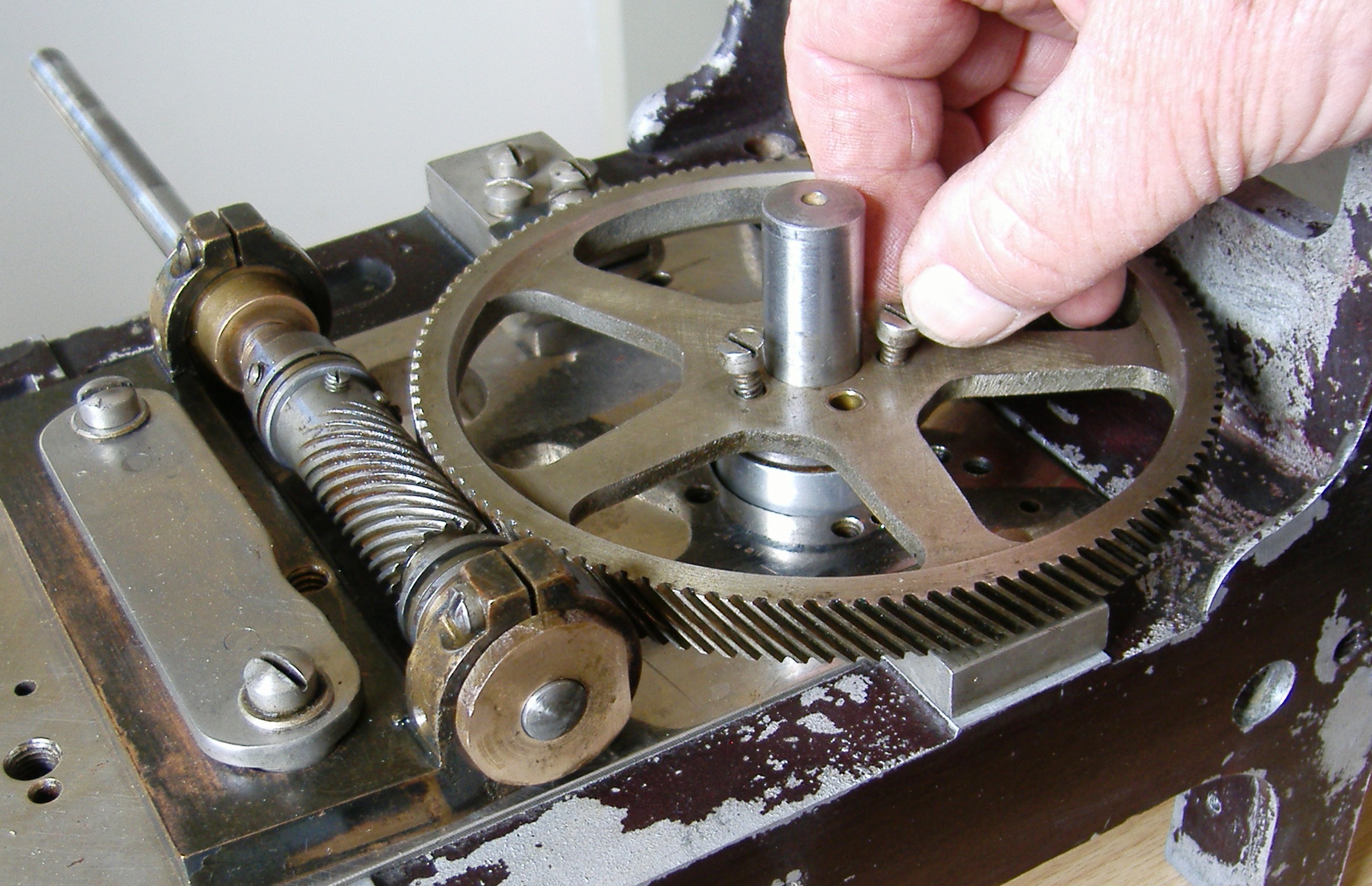
Main drive gear is ready to fit
There is a very indistinct V scribed on to the face of the gear, this fits to the spindle gear (I’ll have to get rid of the rust marks in the spindle gear) . You might just make out the mark . This aligns the 5 fixing screws The flange cut on the main bearing shaft should be at the lowest point.
In go the fixing screws helped by a spot of light oilNip up the screws and spin the gear wheel and check for free movement
Make sure the spindle is fully oiled; this will impart oil to the gear teeth Carefully wipe of excessive oil If the gear shaft does not run truly then it must be re-installed in a new position
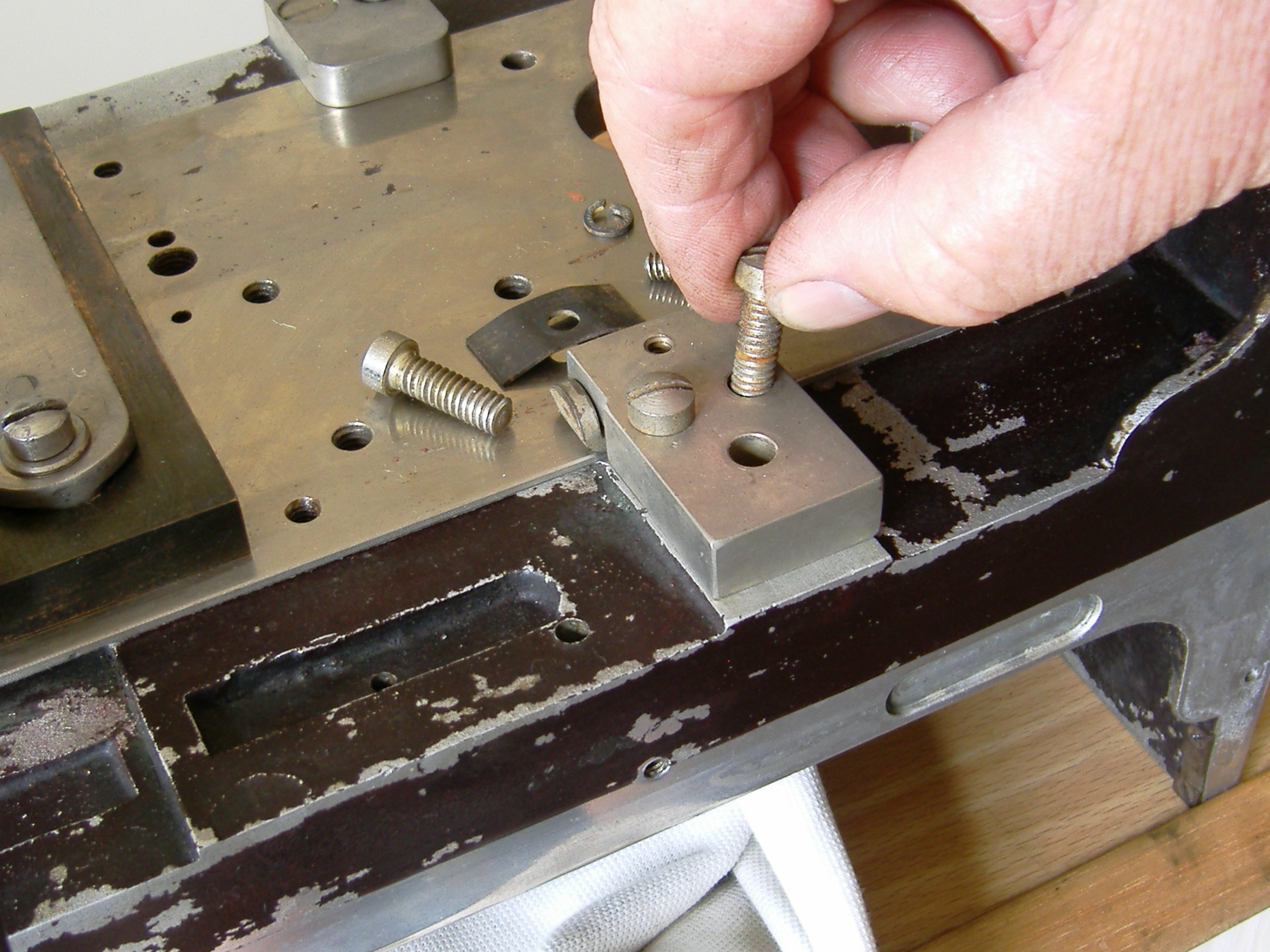
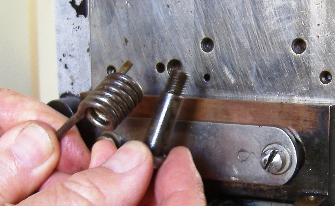
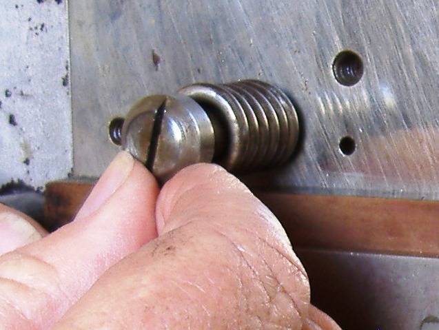
Stud and Tension Spring attachment to the Slider Framing adjusting Spindle holder
Strong Tension Spring and Stud
Locate the short end of the spring and guide it into the end holding hole which is left of the centre fixing screw hole
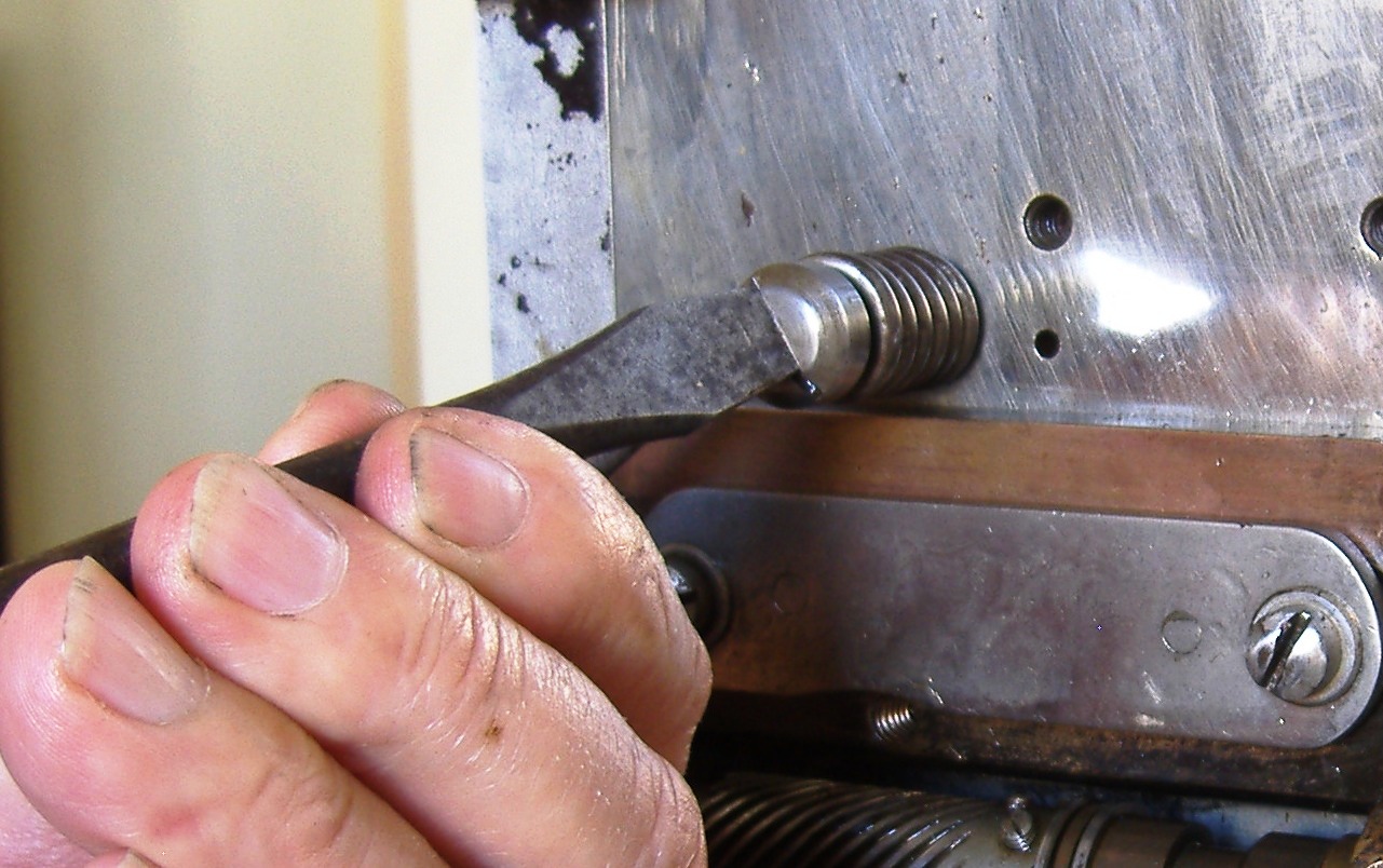
The holding screw turned into the frame through the spring
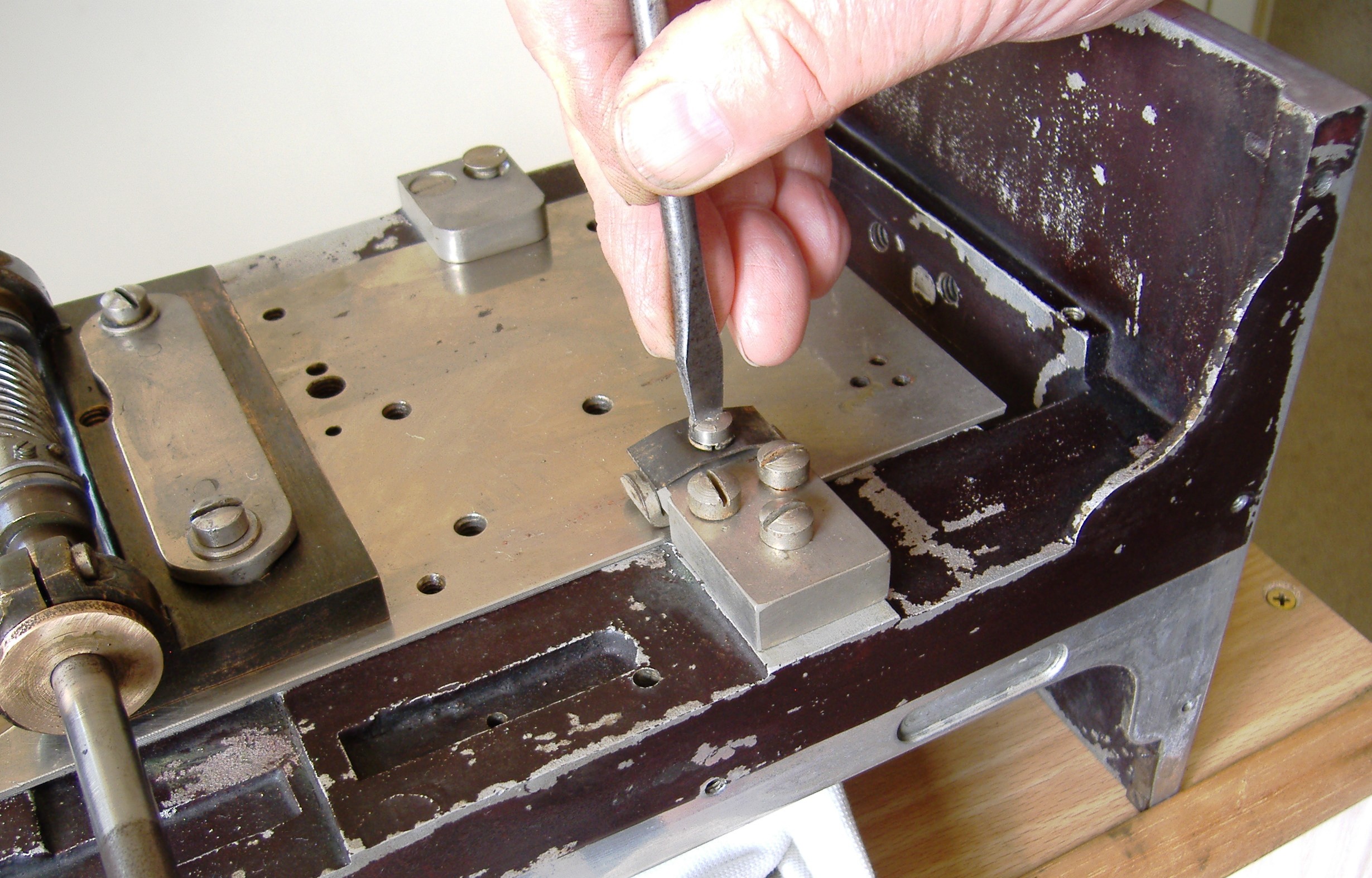
With a large pointed screw driver tighten up the holding screw
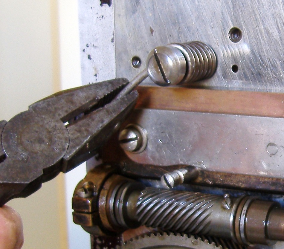
With a heavy pair of pliers grab and turn the tail end of the spring to the right capturing the retaining stud
THIS REQUIRES A STRONG PAIR OF HANDS
This should be done quickly with a positive action because the spring is very strong indeed
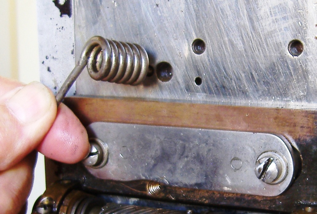
NOTE CAUTION: DON’T INSET THE LEFT VERTICLE FRAMING SPRING STUD BEFORE YOU ATTEMPT PUT THE CAPTURE STUD
BECAUSE IF YOU DO, AND YOU HAPPEN TO LET GO OF THE PLIERS ACCIDENTLY
THE SPRING WILL SPRING BACK AND SNAP OFF THE VERTICAL FRAMING STUD WITH A BANG!
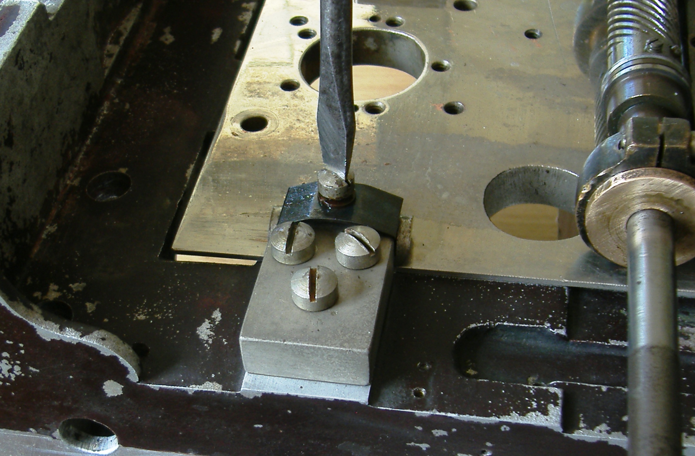
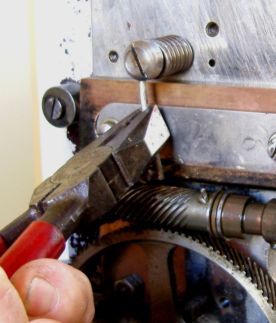
Once in position, push the tail end of the spring behind the retaining stud with a quick downward movement of the pliers
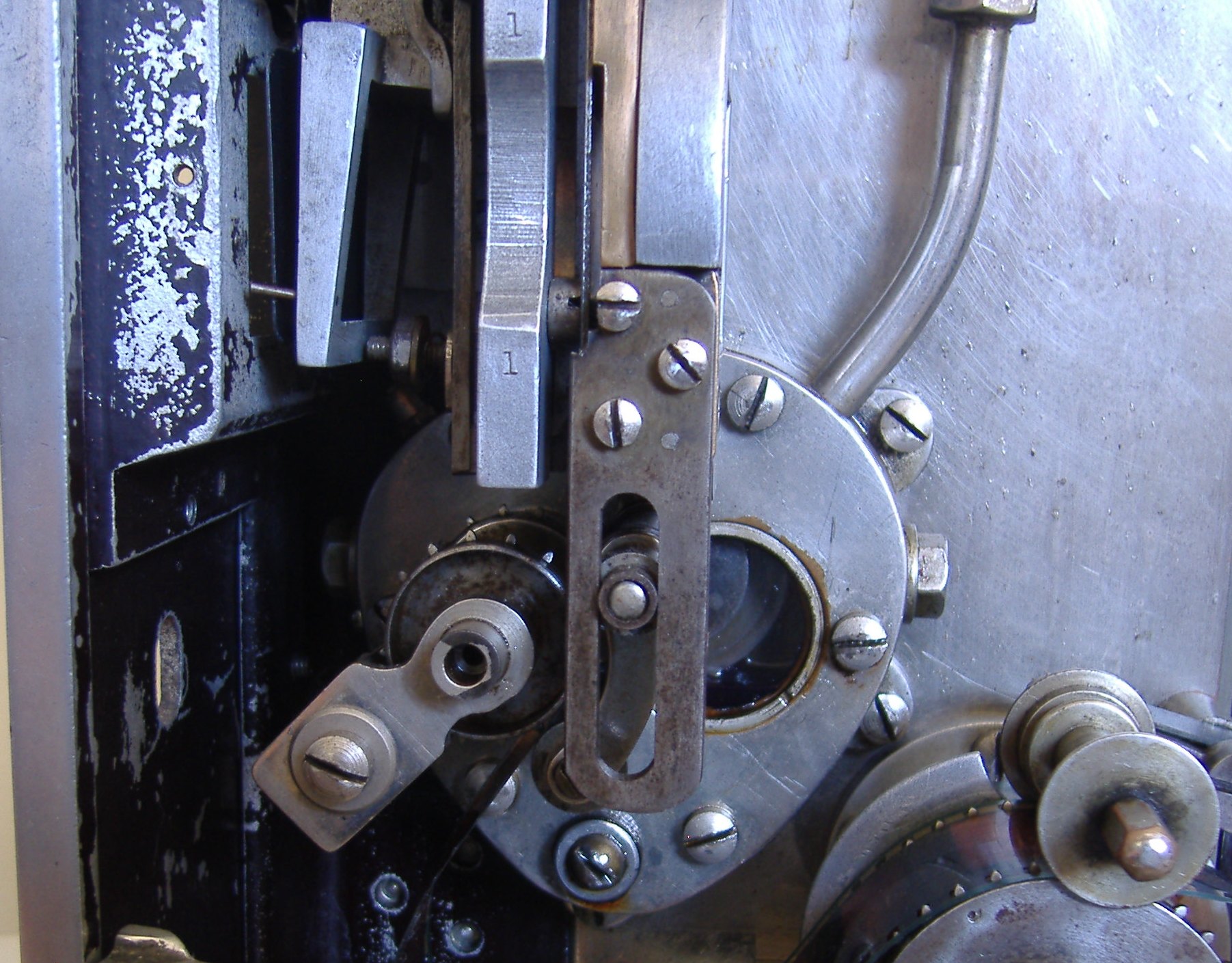
It’s now in place and the angle ended slider takes up a position against Framing Adjustment Roller at the left. This will often make the slider to move to the left
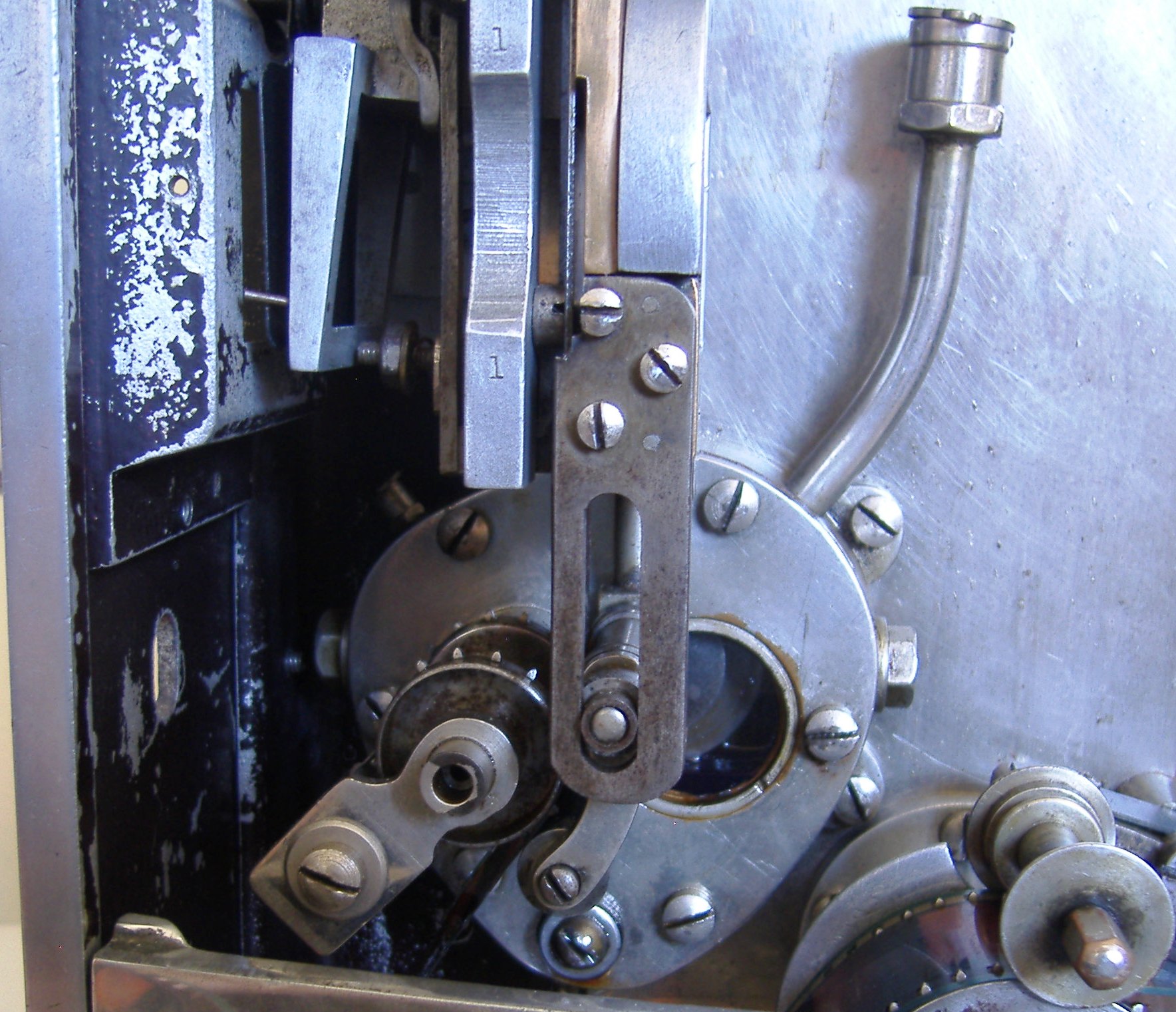
Spinal Frame Adjusting Roller
Roller set in middle position Spindle frame and gear to Shutter in good alignment
As the main frame carrying the Intermittent, spindle and shaft to the fan shutter is the main feature of the all Senior models to control the film framing
The spindle and shutter opening and closing timing has to remain constant
To correct for this the spindle slider is repositioned backward and forward to make the correction by the use of an end wedge shape and roller
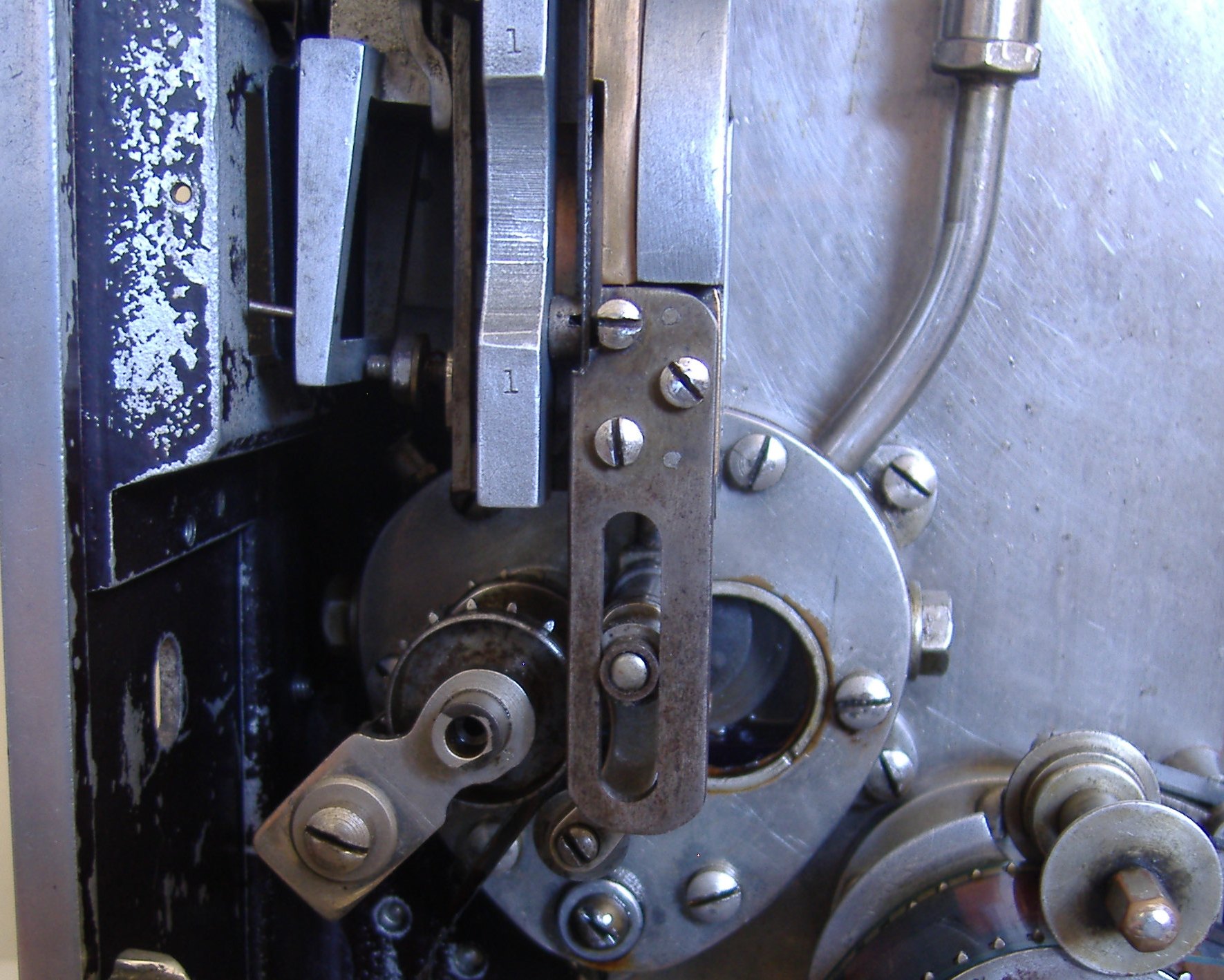
The next pictures show the main farming in the middle, top and bottom of the framing position in the film gate. This is fixed to the outside projection frame, keeping it aligned with the lamp source
Roller in top framing position
Operating side top framing position
Middle position normal framing position
Bottom framing position. No framing position is left